It's all Sid's fault. He got me started by mentioning projects he is working on, and I said that I wanted to build an LED cube. I had just gotten a few shift registers to use to follow the DroneBot shift register tutorial. Sid told me about the CharlieCube, a 64 RGB LED display that doesn't use shift registers. Now I'm hooked. I ordered parts this week that should arrive before the weekend. There are many online instructions and videos for this project. The wiring on the underside of the perf board platform is a bit complex, but the instructions are fairly clear. One thing that I cannot find is an image or video that displays the finished wiring. The drawings in the instructions are nice, but the finished board must look like spaghetti. Has anyone seen a picture or video that shows what that actual finished wiring on the underside of the perf board looks like? I only have primary colored hookup wire. I will have to tag the wires somehow. It has only 16 connections to digital pins on an Arduino Nano. Amazing 😉
One of the articles I read helped to clarify how this cube works. The microcontroller pins can be placed in three states; two as outputs, HIGH and LOW, and one as input with pullup that effectively disconnects the pin (off). The CharlieCube library for Arduino includes the mappings.h header file that defines the LED pin mappings, 64 for each color. Using a very cleaver scheme, each color element of each LED can be lit by placing certain pins in one of three states. There is some current blead through apparently, and some LEDs may light dimly. The display does look brilliant in the videos I've seen. The library includes many example sketches. I will post pics and vids of my project in progresses. Does anyone else here have any experience building a CharlieCube?
ZoolanderMicro, where small ideas are a big deal
I got one of my parts orders yesterday. I love it when packages arrive early. What's in the box? This order has the perf board for the base and circuitry of the project, a Bag-O 100 tri-colored LEDs, and a variety of resistor values that I need for completing my TwinklingLights_20 boards. Jameco sells a kit of parts for constructing a CharlieCube, and it includes LEDs with slightly lower forward voltage thresholds than the ones I ordered. Those have a Vf of 1.9/3.0/3.0. The ones I got were cheaper and have a Vf of 2.0/3.2/3.2. I hope these will be OK. By the hundred, they are only $0.29 each. I am documenting this project, taking pics and vids as I go.
ZoolanderMicro, where small ideas are a big deal
I sniped this image from instructions provided with the Jameco kit. It shows the wiring on the underside of the perf board. Looks easy, right? We'll see how it goes. If I post pictures of the finished wiring, it may be the only instance of an image of this on the Web. I still cannot find any pictures or videos showing the finished wiring.
ZoolanderMicro, where small ideas are a big deal
I've always wanted to make one of these, you'll need a lot of solder for this project!
These displays use a display multiplexing technique called "Charlieplexing", named after Charlie Allan at Maxim who invented it about 25 years ago. I have considered building one as a DroneBot Workshop project, and may still do so one day.
For those less brave there are also kits with PCBs to simplify wiring. For those who like a challenge, many people have built these on one circuit board, using stiff wires to support the whole thing.
Keep us posted!
😎
Bill
"Never trust a computer you can’t throw out a window." — Steve Wozniak
Just thinking about the amount of soldering, combined with the confined space yer soldering in, makes me want to go jump off a cliff
Good Luck !
Hi Spyder, the pin headers are already soldered to the Nano board. I just ordered single row, 16 pin socket headers for the perf board. I will be able to plug the Nano onto the board, but it won't be totally dedicated to it. I am thinking of running the wires on the top side of the board. I think I can do a neat enough job to display it. Or, it may look like a Borg cube (Resistance is futile, you will be assimilated).
ZoolanderMicro, where small ideas are a big deal
One thing that I cannot find is an image or video that displays the finished wiring.
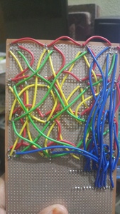
Here you go
I did not plan to do it this way - I wanted to have different colors for different sets but it was during the lockdown and I could not get any of those Ribbon Cables back then. So it looks cluttered with Red wire being used most.
Life is exploring and learning
These displays use a display multiplexing technique called "Charlieplexing", named after Charlie Allan at Maxim who invented it about 25 years ago
I never could study Electronics at school or as an education. I have been hooked on to your videos on YouTube (these are what got me here). I would love you explaining the concept of CharliePlexing - it just might open up more exciting doors for me.
Life is exploring and learning
I am thinking of running the wires on the top side of the board. I think I can do a neat enough job to display it. Or, it may look like a Borg cube (Resistance is futile, you will be assimilated).
Tried that kind of wiring to avoid the clutter on the back - but as my wires are thick, they ruined the display when it started. Avoid it. Borg is not always good 😛
Life is exploring and learning
Just thinking about the amount of soldering, combined with the confined space yer soldering in, makes me want to go jump off a cliff
My first attempt was (as mentioned on the site - using the 1.2mm thick wires). But I miserably failed and the re-attempting made me feel worse. (You cannot go on soldering with trembling hands). So I got rid of those wires and soldered the endpoints of the RGB LED of one to the top of the other - Dont forget to mark off the RED lead on every LED - that helps keeping things oriented.
Life is exploring and learning
Hi Sid, I've been offline for a week. Thanks for posting your picture of the wiring. I will take your advice and run the wires on the underside. I made my first CharlieCube spire. Stretching the wire worked out better than I thought it would. It was still a challenge to complete the spire. My first attempt was successful. I learned a lot and I will refine my technique. I found some code for testing a single spire written by Steve Yoshida (StevesProjectPages.com). His code lights the RGB elements of each LED. After reading and figuring out how it works, I decided to expand on it to create more patterns. Attached is my code written for an Arduino Nano. I like the way it looks, so I am dedicating my first spire to it's own board driven by an ATtiny45 microcontroller. Here is a video:
ZoolanderMicro, where small ideas are a big deal
This spire looks sooooooo cute. (sorry for those extra o's, couldn't help it, in love with that one already.)
Hi Sid, I've been offline for a week.
I was getting concerned owing to the world conditions and also the winters you mentioned earlier. Glad that you spent time getting this lovely piece assembled. After this response here, I am heading to YouTube and subscribing you.
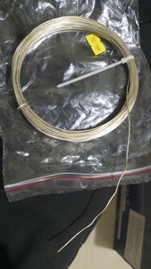
Oh, can you please share the URL you got that wire(s) for the spire for!. As I mentioned, those half-hard or half soft wires are not available here in India. And the last one that came in is (18 Gauge) 1+ mm thick and quite stiff. Am worried if I can ever get that straightened up. Am attaching a pic of it as well.
And another sad news is that my order of 1000 RGBs from AliExpress has been cancelled because of political issues between India (my country) and China. As such, I have to postpone the RGB cube. However, I have managed to order 600 blue leds from a local seller in India. Expected date of arrival is 26th Dec. I have about 70 Common Cathode RGBs still with me, so I will try making those spires again (the way you did it will be handy to know. I hope you will update those tricks on the post as well).
So for the time being I am attempting a Matrix of 10x10 red leds - where I can experiment and get Happy Birthday light up (one alphabet a time) for my daughter who turns 5 this 13th.
Here is the pic of the wire that came in a couple of days back.
Life is exploring and learning
@Sid I was surprised by how much the 20 gauge copper wire stretched. After stretching, it became very rigid and straight.
I clamped one end of the wire to the bench and clamped the other in vise-grip plyers. Using a short piece of wood as a fulcrum, I pushed down on the handles of the plyers until I could feel some resistance. Sometimes the wire would break at the jaws of the plyers.
You can see how the wire stands very straight after stretching.
I don't remember the supplier, but I keep all of my invoices. I will post a link to the 20 gauge bare copper wire. There are many Amazon sellers too.
ZoolanderMicro, where small ideas are a big deal
Sounds like doable to me. I will have to find something to keep it straight (similar to the wooden plank that you used). I can also experiment with other things. The only concern is that the one they delivered this time is 18 gauge (almost 0.4mm thicker, but that should still work, right?) Tomorrow or day after (as tomorrow is my wife's office), I am going to find one plank to start with.
Life is exploring and learning


