I have searched the internet, searched multiple forums, and even taken courses in programing the Arduino. I have found detailed videos of controlling servos with an encoder, and controlling a dc motor with an encoder. Unfortunately I have not been able to find any information that specifically deals with the application I am trying to program. I am trying to take input from an independent incremental optical rotary encoder, one not attached to a motor, and use it with the Arduino uno and a motor controller to control a DC linear actuator. I am using this setup to control the trim system on a flight simulator I am building. When the trim is actuated on my simulator, whether manually or electrically, the shaft attached to the rotary encoder with turn causing the encoder to spin. It will either spin clockwise or counter clockwise depending on the direction the trim is being adjusted. I want to use this input to activate the linear actuator to either extend or retract based on the clockwise or counter clockwise movement of the encoder. When the encoder stops moving, the linear actuator needs to stop as well. The speed the encoder will spin will be at a low and high speed and a variable speed if trim is adjusted manually. The video I saw that was helpful was using an encoder to control a servo. But I can't use a servo in this application as a servo is not powerful enough. I appreciate any help you can provide. I hope this is enough information to start to get some assistance in solving my problem. Thanks.
@tckellogg Good information. Start with the servo sketch or the motor sketch you found and simply replace the servo or motor with the actuator. You will probably need to 'map' the servo signal to appropriate linear actuator signals. Look Here the DC motor example is probably your best bet. Both examples you mention however are fundamentally different in that they are limitless. Your actuator has a minimum and maximum extension so your trim wheel/encoder when it gets to the 'end' of it's input can either just continue to spin with NO effect on the actuator (see the map statement above) or build in mechanical stops.
I have no idea how the actuator is wired, and subsequently what pins you need on an arduino so it might be more complicated than I think but the concept is not too difficult, the map function is your friend.
First computer 1959. Retired from my own computer company 2004.
Hardware - Expert in 1401, and 360, fairly knowledge in PC plus numerous MPU's and MCU's
Major Languages - Machine language, 360 Macro Assembler, Intel Assembler, PL/I and PL1, Pascal, Basic, C plus numerous job control and scripting languages.
Sure you can learn to be a programmer, it will take the same amount of time for me to learn to be a Doctor.
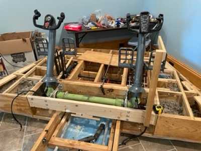
Here you can see the control columns and rudder pedals from an actual 737 I am using to build my simulator. I am using a DC Linear Actuator and springs to simulate changes in control forces similar to what an actual plane experiences in changing flight configurations. When the aircraft needs to be trimmed to alleviate control forces on the flight controls the trim is activated either manually or electrically which turns the trim wheels, (not Pictured above) this turns a shaft which is attached to the incremental optical encoder. I wish to take the input from the encoder and use it to activate a DC linear actuator to extend, stop, or retract based upon clockwise, stationary, or counter clockwise movement of the encoder. The extension or retraction of the actuator increases or decreases forces acting on the flight controls.
@tckellogg YUP, been to flight school, I know what you mean.
First computer 1959. Retired from my own computer company 2004.
Hardware - Expert in 1401, and 360, fairly knowledge in PC plus numerous MPU's and MCU's
Major Languages - Machine language, 360 Macro Assembler, Intel Assembler, PL/I and PL1, Pascal, Basic, C plus numerous job control and scripting languages.
Sure you can learn to be a programmer, it will take the same amount of time for me to learn to be a Doctor.
@tckellogg Does this help, all that is needed is to read the encoder and map it's values to the digital writes to the actuators. Since encoders are freewheeling, you will need to use program logic to assign map value inputs. What I mean is count the encoder signals but only untik a max value then no more, this might be 1 to 1024 for example.
https://www.firgelliauto.com/blogs/tutorials/how-do-you-control-a-linear-actuator-with-an-arduino
Here is another good example, just needs to be modified to use the encoder as input.
First computer 1959. Retired from my own computer company 2004.
Hardware - Expert in 1401, and 360, fairly knowledge in PC plus numerous MPU's and MCU's
Major Languages - Machine language, 360 Macro Assembler, Intel Assembler, PL/I and PL1, Pascal, Basic, C plus numerous job control and scripting languages.
Sure you can learn to be a programmer, it will take the same amount of time for me to learn to be a Doctor.
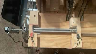
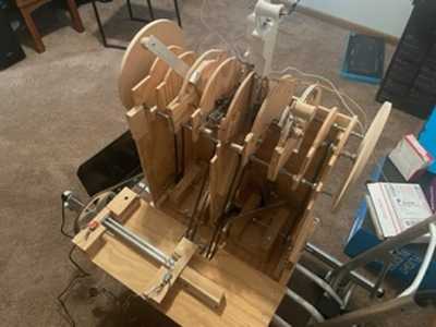
Thanks Ron. No need to worry about limits as I already have addressed this. The shaft the encoder is attached to has fittings attached to it that have limit switches that activate to stop the motor activating the trim wheels in either directions. So once they reach their limit the encoder stops. If I understand this correctly. Here is a picture of a throttle mockup I am using to test before I hookup my actual throttle. Next to it you can see the shaft with the encoder attached and the limit switches.
Thanks for the advice. Hopefully I can work on it after work.
@tckellogg Excellent. This makes it easier. simply install the encoder (pot), hook up an arduino and analogue read sketch and print out the values from one extreme to the other. Now look up map, now determine the max and min numbers for the actuator motor drivers. Fill in the map statements with the results of those two exercises.
First computer 1959. Retired from my own computer company 2004.
Hardware - Expert in 1401, and 360, fairly knowledge in PC plus numerous MPU's and MCU's
Major Languages - Machine language, 360 Macro Assembler, Intel Assembler, PL/I and PL1, Pascal, Basic, C plus numerous job control and scripting languages.
Sure you can learn to be a programmer, it will take the same amount of time for me to learn to be a Doctor.
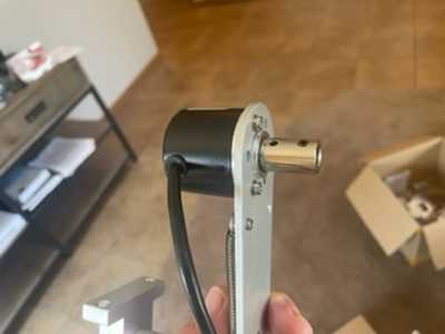
@tckellogg When you say encoder, do you mean what I call a potentiometer or a disk with slots in it. Both can work, the pot is a trivial modification to any actuator sketch with an L298 motor controller like this one.
https://arduinogetstarted.com/tutorials/arduino-actuator
In the examples they run the actuator to the limits, just replace the HIGH and LOW with values from the encoder that have been 'mapped' to actuator values.
First computer 1959. Retired from my own computer company 2004.
Hardware - Expert in 1401, and 360, fairly knowledge in PC plus numerous MPU's and MCU's
Major Languages - Machine language, 360 Macro Assembler, Intel Assembler, PL/I and PL1, Pascal, Basic, C plus numerous job control and scripting languages.
Sure you can learn to be a programmer, it will take the same amount of time for me to learn to be a Doctor.
@tckellogg Ok, different device but similar function. I see there are YT vids on reading it so again, determine max and min values and put them in the map function in the input side.
First computer 1959. Retired from my own computer company 2004.
Hardware - Expert in 1401, and 360, fairly knowledge in PC plus numerous MPU's and MCU's
Major Languages - Machine language, 360 Macro Assembler, Intel Assembler, PL/I and PL1, Pascal, Basic, C plus numerous job control and scripting languages.
Sure you can learn to be a programmer, it will take the same amount of time for me to learn to be a Doctor.

