@farzad_k I have a bunch of different ESP's but I don't know python so I only use C and a tiny bit of C++. I have not encountered the problems you had. In fact, I can run the same code on any number of boards like esp8266, esp32, Arduino, Raspberry Pi as long as I am not using any unique features. Your brief requirements statement tells me this would be a one page or less sketch.
First computer 1959. Retired from my own computer company 2004.
Hardware - Expert in 1401, and 360, fairly knowledge in PC plus numerous MPU's and MCU's
Major Languages - Machine language, 360 Macro Assembler, Intel Assembler, PL/I and PL1, Pascal, Basic, C plus numerous job control and scripting languages.
Sure you can learn to be a programmer, it will take the same amount of time for me to learn to be a Doctor.
I am looking to build a simple circuit that audibly warns when the current out of a 12v DC battery has been interrupted.
@zander went way over my pay-grade with the Victron stuff and when you showed a circuit you want to use, I almost baled on offering this to your thread. As I'm limited on hardware understanding, I try to make the few tools I know work. "When you are a hammer everything looks like a nail."
Aside from the buzzer, what else do I need (non-arduino) that can sense the power outage (V-in=0) and then activate the buzzer circuit?
Thanks for any suggestions.
Also, I wasn't sure if this meant, you didn't want a microprocessor solution, but you also said any solutions. 😆
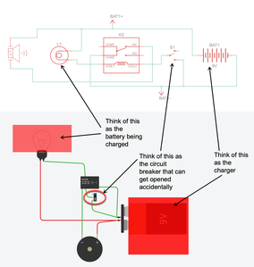
Anyway... another insomnia night... so I'll just throw this out and see if anything sticks. If I understand your problem correctly, you have something like this. I'm imagining a 12V car battery on a car charger with the circuit breaker thrown in between.
Is it good enough to catch the broken circuit breaker before the battery is depleted or do you want immediate gratification? 😋
My first (and only) thought was why not just monitor the voltage output of the battery with a voltage divider and the analog pin on an MPU? While charging, the voltage typically reads something like 14V. If the charger turns off, it fairly quickly drops to 12 to 13V depending on SOC. As it gets drained by your usage, it drops from there.
I'd think...
- ESP8266 <$3
- DC-to-DC voltage converter <$1
- Couple of resistors for a voltage divider tuned to your maximum charger voltage < $0.02
- A scavenged piezo speaker
... should do it.
I'd think the Sketch would be less than 10 lines of code to check the Analog input, scale the voltage and if it falls under say 14V, you know the charger is not charging. Me... I'd probably have the ESP8266 connect to my WiFi and and alert (email) me. But if you really want a buzzer... I've never tried it, but I think you can just hook up a speaker to a digital pin and send a PWM signal to it and it'll buzz.
Hope this helps.
VBR,
Inq
3 lines of code = InqPortal = Complete IoT, App, Web Server w/ GUI Admin Client, WiFi Manager, Drag & Drop File Manager, OTA, Performance Metrics, Web Socket Comms, Easy App API, All running on ESP8266...
Even usable on ESP-01S - Quickest Start Guide
Although probably pretty remedial for you... I remember a few guys (prominently @inst-tech) helped me out on monitoring voltage with the Analog pin. One of those new tools in the bag of tricks. 😉
... so only one resistor is necessary.
3 lines of code = InqPortal = Complete IoT, App, Web Server w/ GUI Admin Client, WiFi Manager, Drag & Drop File Manager, OTA, Performance Metrics, Web Socket Comms, Easy App API, All running on ESP8266...
Even usable on ESP-01S - Quickest Start Guide
@inq Except when it finishes absorb charge it drops to float at 13.5 or 13.6. Either will work the poster's solution is simpler and more reliable.
First computer 1959. Retired from my own computer company 2004.
Hardware - Expert in 1401, and 360, fairly knowledge in PC plus numerous MPU's and MCU's
Major Languages - Machine language, 360 Macro Assembler, Intel Assembler, PL/I and PL1, Pascal, Basic, C plus numerous job control and scripting languages.
Sure you can learn to be a programmer, it will take the same amount of time for me to learn to be a Doctor.
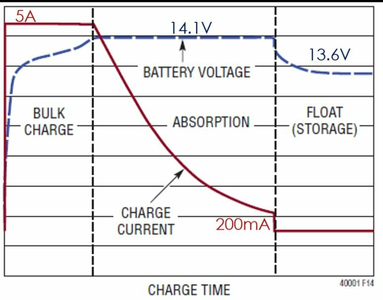
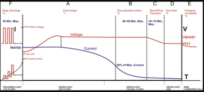
@inq Since a lead acid battery spends most of its time at less than the absorb voltage of 14.x the buzzer would be mostly on. See pic for a typical lead acid battery charge, there are slight differences in voltages at the 1st decimal position depending on type of lead acid, sealed vs not sealed. A sophisticated solution is a shunt with capacity calculations over time. If the capacity is on a constant down trend then that may be a problem but the OP has produced a simple cheap design that meets his requirements. 2nd pic is more accurate. Neither picture shows the resting time needed. Here is an excerpt from a lengthy article on Lead Acid charging
Another factor is that freshly charged batteries have a high concentration of acid next to the plates due to the formation of sulphuric acid on a charge. This is why the voltage after charging remains high for some time perhaps up to 48 hours before settling at a consistent value. Unless a short discharge is made to the battery then it has to rest to allow equalisation of the acid concentration before taking a voltage reading.
First computer 1959. Retired from my own computer company 2004.
Hardware - Expert in 1401, and 360, fairly knowledge in PC plus numerous MPU's and MCU's
Major Languages - Machine language, 360 Macro Assembler, Intel Assembler, PL/I and PL1, Pascal, Basic, C plus numerous job control and scripting languages.
Sure you can learn to be a programmer, it will take the same amount of time for me to learn to be a Doctor.
Since a lead acid battery spends most of its time at less than the absorb voltage of 14.x the buzzer would be mostly on. See pic for a
You are wrapping around an unknown wheel.
- If you understand that his hardware solution is better, I certainly have no ability to dispute that. I take your and his word for it that it is better. Go with that, live long and prosper!
- There was no mention of the type of battery he is using. Me, myself and I simply used that as an example to explain the concept of the MPU suggestion. His O.P. sounded like he is using a continuously charging system. As we all know that is a bad idea for lithium batteries, I simply assumed lead-acid, car battery. If you will re-read the O.P., you'll see he said, "he wants to know when it is NOT CHARGING", thus in a lead acid car battery that is when it is below 14V. Either way, I am sure he is (AND you) are certainly smart enough to realize that he can set thresholds to his heart's content. Since ONLY he knows what his system is based on and how he wants it to respond, ONLY he can set those voltages. My numbers were purely an EXAMPLE of how HE might set it up. As his O.P. said the purpose is so that it doesn't drain the battery, he could set them to some value that clearly says... something is SNAFU like 12.0V. The concept I proposed is valid and would work to his O.P. specifications as currently known.
If I knew how to create the circuit he came up with, I too would certainly use it. KISS principle is best! However, if the thing was in the basement, I would rather have the MPU voltage checking version. That way I could monitor the voltage from anywhere, versus having to hear a buzzer through the floor. But again, we have no idea what is situation is.
3 lines of code = InqPortal = Complete IoT, App, Web Server w/ GUI Admin Client, WiFi Manager, Drag & Drop File Manager, OTA, Performance Metrics, Web Socket Comms, Easy App API, All running on ESP8266...
Even usable on ESP-01S - Quickest Start Guide
@inq Actually what he wanted is to know when someone opened the switch that then prevented the battery from charging so the voltage went from some value to 0. That is why the circuit is designed the way it is.
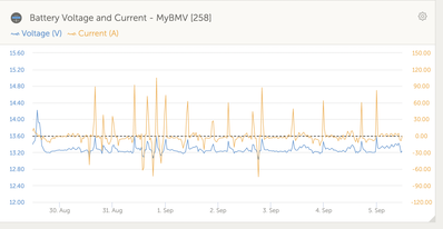
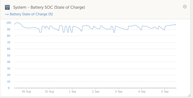
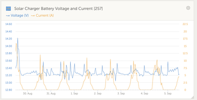
I have included a chart of my battery bank voltage and current for one week. I am also enclosing a state of charge chart for the same period as well as the solar charger output. You will note the state of charge fluctuates between 85 and 95 generally, and on really sunny days will hit 100%. My point is battery charging is happening as the chart shows, but the voltage needed to do that is well below 14V. If you like I can zoom into these charts to show you the battery being charged between 2330 and 1030 during the last 24hrs if you can't see that level of detail and you will see the charger kicked on based on time of day for 1 hr or 95% but by 1020 this morning had risen to 97%. Charging is happening at 13.3V to 13.4V. I will be happy to give you access to my installation on the Victron monitoring site, just let me know by PM and I will send you the private URL.
First computer 1959. Retired from my own computer company 2004.
Hardware - Expert in 1401, and 360, fairly knowledge in PC plus numerous MPU's and MCU's
Major Languages - Machine language, 360 Macro Assembler, Intel Assembler, PL/I and PL1, Pascal, Basic, C plus numerous job control and scripting languages.
Sure you can learn to be a programmer, it will take the same amount of time for me to learn to be a Doctor.
Hello folks.
Allow me to clarify that the intent is not at all to trigger a buzzer based on certain voltage; the intent is to trigger the buzzer if current in a circuit goes to zero.
In the schematics I came up with yesterday you see the solution that I think works for me. I have a relay that is ordinarily open in the buzzer circuit, keeping it from buzzing. This relay gets closed if the current in the main circuit is disrupted. The simulation here uses a switch, which is really what the circuit breaker is and does when its button is accidentally pressed.
I created this model in TinkerCad.
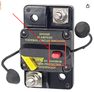
The battery being charged is an auxiliary battery inside the vehicle and is a LifePO4. The charge controller is also inside the vehicle and is a RedArc1225 charge controller that delivers power to the LifePO4 from the car's alternator (when engine is running) and solar panels (when connected). The breaker sits between the RedArc and the LifePO4, protecting the RedArc. We have the same circuit breaker in between the alternator in the engine compartment and the RedArc that sits inside the vehicle near the LifePO4.
Farzad
I wonder if this relay works; there is no wiring schematics. Or this one?
@farzad_k Any 12V relay with at least 1 normally CLOSED contact will work. I do not think either one of those 2 will work.
The first one requires a 5V logic level signal from an arduino or ESP etc. The 2nd one is some sort of special use that I don't understand.
First computer 1959. Retired from my own computer company 2004.
Hardware - Expert in 1401, and 360, fairly knowledge in PC plus numerous MPU's and MCU's
Major Languages - Machine language, 360 Macro Assembler, Intel Assembler, PL/I and PL1, Pascal, Basic, C plus numerous job control and scripting languages.
Sure you can learn to be a programmer, it will take the same amount of time for me to learn to be a Doctor.
@farzad_k 12VDC SPDT current rating to match the lightbulb. A 10W bulb will use less than 1A.
OOPS, that isn't a light bulb, it's the battery on the charger! That could be 50A and the relay will cost a fortune.
First computer 1959. Retired from my own computer company 2004.
Hardware - Expert in 1401, and 360, fairly knowledge in PC plus numerous MPU's and MCU's
Major Languages - Machine language, 360 Macro Assembler, Intel Assembler, PL/I and PL1, Pascal, Basic, C plus numerous job control and scripting languages.
Sure you can learn to be a programmer, it will take the same amount of time for me to learn to be a Doctor.
@farzad_k Why not just mount the CB in a plastic box?
First computer 1959. Retired from my own computer company 2004.
Hardware - Expert in 1401, and 360, fairly knowledge in PC plus numerous MPU's and MCU's
Major Languages - Machine language, 360 Macro Assembler, Intel Assembler, PL/I and PL1, Pascal, Basic, C plus numerous job control and scripting languages.
Sure you can learn to be a programmer, it will take the same amount of time for me to learn to be a Doctor.
@zander 😀 I was thinking about that same thing last night: ounce of prevention instead of pound of cure: why not keep the accident from happening in the first place. All that I really need to do is to 3-D print a casing larger and taller than the red button and glue it to the body of the circuit breaker so the button can only be pushed intentionally.
@farzad_k What size battery, I assume 100AH. What is the max current in the charger circuit. Given first assumption and assume a 0.5C charge there will be 50A in the charge circuit.
Are you using 4awg wires.
There are hidden dangers in this, why not just prevent the problem from happening in the first place. Who is tripping the CB, why are they tripping the CB?
First computer 1959. Retired from my own computer company 2004.
Hardware - Expert in 1401, and 360, fairly knowledge in PC plus numerous MPU's and MCU's
Major Languages - Machine language, 360 Macro Assembler, Intel Assembler, PL/I and PL1, Pascal, Basic, C plus numerous job control and scripting languages.
Sure you can learn to be a programmer, it will take the same amount of time for me to learn to be a Doctor.


