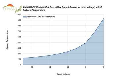
@tracecom It looks the same to me. Where/how are you seeing the surge? The usual fix is a cap and you have it. Is it installed correctly?
First computer 1959. Retired from my own computer company 2004.
Hardware - Expert in 1401, and 360, fairly knowledge in PC plus numerous MPU's and MCU's
Major Languages - Machine language, 360 Macro Assembler, Intel Assembler, PL/I and PL1, Pascal, Basic, C plus numerous job control and scripting languages.
Sure you can learn to be a programmer, it will take the same amount of time for me to learn to be a Doctor.
@tracecom Ok, what makes you think that the PICO is pulling a lot of power? Symptoms, ill-effects?
First computer 1959. Retired from my own computer company 2004.
Hardware - Expert in 1401, and 360, fairly knowledge in PC plus numerous MPU's and MCU's
Major Languages - Machine language, 360 Macro Assembler, Intel Assembler, PL/I and PL1, Pascal, Basic, C plus numerous job control and scripting languages.
Sure you can learn to be a programmer, it will take the same amount of time for me to learn to be a Doctor.
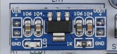
@will I think he is using an LMS1117 module with support circuitry. I have the same modules and have used them with no issues. The pic is from his pcb pic.
First computer 1959. Retired from my own computer company 2004.
Hardware - Expert in 1401, and 360, fairly knowledge in PC plus numerous MPU's and MCU's
Major Languages - Machine language, 360 Macro Assembler, Intel Assembler, PL/I and PL1, Pascal, Basic, C plus numerous job control and scripting languages.
Sure you can learn to be a programmer, it will take the same amount of time for me to learn to be a Doctor.
What's shown on the schematic does not include the components that are on the AMS1117-5 module; all the circuitry required to support the AMS1117 chip are on the module. See my photos and look closely at the blue module. Bill says in his video that the Mini-360 may be replaced with another switching regulator or a linear regulator. I have built and used dozens of linear regulators in the 78XX series and the LM317; they are not as efficient as switching regulators, but they create much less electrical noise. I have used the AMS1117-5 module only once before, and it performed with no problems.
Here's what seems to happen a lot (but not all) of the time. I have the complete RPi Pico Pack assembled as per the schematic. I plug in the USB, and all is well. I unplug the USB (which isn't really necessary due to the presence of D1,) and then plug in the external 12V supply. Some of the time, all is well, but some of the time, the AMS1117-5 Module fails. The only reason that I have thought of that seems logical is that the RPi Pico draws more current at startup than the AMS1117-5 module can supply. I am wiring up a new AMS1117-5 module, and am going to test it by starting off with a small resistive load, and then decreasing the resistance in steps to see at what current it fails. If I knew the startup current of the RPi Pico, that would be a great help, but I haven't found it in the data sheet. So, I may have to try to measure that as well, but I haven't really thought of a good (and simple) way to do that.
I have some Mini-360 modules that will arrive on Monday afternoon, and if necessary, I will substitute that in my PCB. Long term, that will mean a new PCB layout, but short term, I can fly-wire them into the current design.
Of course, there certainly could be some other issue that I don't yet know about. I feel confident that if Bill's protoboard circuit works properly, I can make my PCB work as well.
Thanks for your interest.
@tracecom I agree, it should work with the 1117, I have used them as substitutes several times with no issues. Very strange, keep us informed, I have a feeling there is a lesson in there somewhere.
First computer 1959. Retired from my own computer company 2004.
Hardware - Expert in 1401, and 360, fairly knowledge in PC plus numerous MPU's and MCU's
Major Languages - Machine language, 360 Macro Assembler, Intel Assembler, PL/I and PL1, Pascal, Basic, C plus numerous job control and scripting languages.
Sure you can learn to be a programmer, it will take the same amount of time for me to learn to be a Doctor.
The only documentation I could find wasn't too encouraging. It said ...
Our AMS1117 5V voltage regulator modules are rated at 800mA maximum output current. However, it is a linear regulator, not a switching converter. The module will dissipate a lot of heat if it is asked to handle a higher current with a large voltage drop (difference from Input Voltage to Output Voltage).
This should be considered in your circuit design. The module will not be able to achieve the full 800mA output when the input to output voltage differential is greater than a couple of volts.
Depending on your input voltage, the maximum current available for output will be impacted. The larger the input voltage, the lower the current capabilities.
In this case it's dropping from 12V to 5V so it'll be giving up a lot of power.
If you have a 6V, 7.5V or 9V cable with a plug that will fit this, please try powering it with something less than the 12V. I'm wondering if it's just dropping the output current because it's such a large difference in voltage. The documentation I saw suggested that the output power drops when there's a large deviation in input to output voltage.
IT said ...
Our AMS1117 5V voltage regulator modules are rated at 800mA maximum output current. However, it is a linear regulator, not a switching converter. The module will dissipate a lot of heat if it is asked to handle a higher current with a large voltage drop (difference from Input Voltage to Output Voltage).
This should be considered in your circuit design. The module will not be able to achieve the full 800mA output when the input to output voltage differential is greater than a couple of volts.
Depending on your input voltage, the maximum current available for output will be impacted. The larger the input voltage, the lower the current capabilities.
Anything seems possible when you don't know what you're talking about.
@will I thought Charles was aware of all that, he said he had relevant experience. I almost never use an LDO LVR if the voltage drop is more than 3V, I will stick a BUCK converter in front to take the 12V down to 7ish then onto the 1117 putting out 5V. It got past me that he was going 12 to 5 in one step, I suspect that's too much.
First computer 1959. Retired from my own computer company 2004.
Hardware - Expert in 1401, and 360, fairly knowledge in PC plus numerous MPU's and MCU's
Major Languages - Machine language, 360 Macro Assembler, Intel Assembler, PL/I and PL1, Pascal, Basic, C plus numerous job control and scripting languages.
Sure you can learn to be a programmer, it will take the same amount of time for me to learn to be a Doctor.
@will @zander You may be right. As I said, my experience with this particular device (1117) is limited.
However, I would rather have some numbers to work with before I count it out. I would really like to know what the RPi draws at startup and what the failure point is of the 1117. (I have a very strong bias for linear regulators.)
I have a built and used lot of 78xx regulators from 3.3V to 18V, and not one has ever completely failed; the 78xx devices have a built-in high current protection circuit that shuts them down until they cool off. Apparently, the 1117 doesn't have such protection unless of course the Chinese AMS1117 modules are improperly built.
Thanks again for your help.
ETA: I will experiment with a lower input voltage to the AMS1117-5 module. I know it will help, but if the AMS1117-5 can't tolerate a 12V input for this project, it's a no go.
@tracecom I assume you have not read @will 's post which is an excerpt from the official docs. 12 to 5 is too much.
First computer 1959. Retired from my own computer company 2004.
Hardware - Expert in 1401, and 360, fairly knowledge in PC plus numerous MPU's and MCU's
Major Languages - Machine language, 360 Macro Assembler, Intel Assembler, PL/I and PL1, Pascal, Basic, C plus numerous job control and scripting languages.
Sure you can learn to be a programmer, it will take the same amount of time for me to learn to be a Doctor.
I found some documentation at https://www.pcboard.ca/ams1117-5v-power-supply-module The following is based what it says there.
This should be considered in your circuit design. The module will not be able to achieve the full 800mA output when the input to output voltage differential is greater than a couple of volts.
Depending on your input voltage, the maximum current available for output will be impacted. The larger the input voltage, the lower the current capabilities.
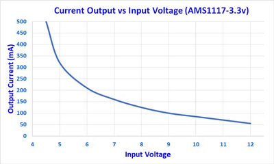
It also has a diagram for the throughput of a 3.3V regulator (I realize that you're using 5V but this is the only chart available and it's instructive)
The 5V chart won't be was dramatic at 12V butI think it spells the end of your use of an LMS117 unless you use a lower supply voltage.
You may get better information if you have access to details for the specific board you have.
Anything seems possible when you don't know what you're talking about.
@tracecom Why can't you replace the 1117 with a MINI-360?
Q2 - what is determining the 12V input, car, boat, RV, solar off grid.
First computer 1959. Retired from my own computer company 2004.
Hardware - Expert in 1401, and 360, fairly knowledge in PC plus numerous MPU's and MCU's
Major Languages - Machine language, 360 Macro Assembler, Intel Assembler, PL/I and PL1, Pascal, Basic, C plus numerous job control and scripting languages.
Sure you can learn to be a programmer, it will take the same amount of time for me to learn to be a Doctor.
@tracecom I am just guessing here, but you seem to be reluctant to use a switching converter. There are newer lower noise or different freq's if you are freq sensitive to choose. Another approach is build a box with a BUCK that takes in 12V and puts out 7V that has a long enough lead and the box is wrapped in some faraday material to allow the BUCK to take the bulk of the conversion.
Are you car, boat, RV, off grid?
First computer 1959. Retired from my own computer company 2004.
Hardware - Expert in 1401, and 360, fairly knowledge in PC plus numerous MPU's and MCU's
Major Languages - Machine language, 360 Macro Assembler, Intel Assembler, PL/I and PL1, Pascal, Basic, C plus numerous job control and scripting languages.
Sure you can learn to be a programmer, it will take the same amount of time for me to learn to be a Doctor.
@will @zander @dronebot-workshop
Okay, I am convinced that the AMS1117-5 is a bad choice for this project. And, as I have said, I have some Mini360 Buck Converters arriving Monday afternoon. I will fly-wire one in and see if there are any problems. Revising my PCB layout should be minor. I have a couple of other minor changes to make. I am also open to suggestions from the forum members (or even Bill himself.)
Let's all smile and be happy.
@zander I want the device to be usable at up to 13.8V in order to accommodate lead acid batteries in cars, boats, RV's, and amateur radio power supplies, however I will continue to mark the PCB 12V max and 7V minimum.
@tracecom I have an off grid RV and built my own solar setup. 13.8 is a strange choice of voltage, for Pb absorb is 14.3ish and LiFePO4 it's 14.5ish, 13.8 is above float which is 13.6, LiFePO4 don't use float. 13.2 is the 'normal' resting voltage, I just looked at my battery bank and it is at 93% and 13.19V. My 'charged voltage' is 14.3 (add.2 to determine absorb)
What exactly are you wanting to do/measure?
First computer 1959. Retired from my own computer company 2004.
Hardware - Expert in 1401, and 360, fairly knowledge in PC plus numerous MPU's and MCU's
Major Languages - Machine language, 360 Macro Assembler, Intel Assembler, PL/I and PL1, Pascal, Basic, C plus numerous job control and scripting languages.
Sure you can learn to be a programmer, it will take the same amount of time for me to learn to be a Doctor.


