Hi i have been working with Arduino for about 2 years and i wanted to start moving away from using modules. i have created a proof of concept circuit and it works well but it uses larger modules that i want to have in a smaller form factor. when I look through the data sheets and I am overwhelmed, so i was wondering if there were specific areas to look at to figure out wiring. pin description area tells me a lot, but does that tell me everything i need to know such as resistors.
any help is greatly appreciated thank you
Hi @tutelertundra76,
Welcome!! We all get overwhelmed from time-to-time, but the usual trick is to try to divide the problem down into manageable bits, each of which, can be tackled on their own.
So can I respectfully suggest you try posting a much more specific question, starting with what you are trying to achieve, (including details of what you are building, etc.) and what you have achieved, and then asking a question where you have got stuck.
It is helpful to start by describing the whole project as background information, and then try to narrow your discussion to the most relevant details, as you approach the question.
Hopefully, if you post a more specific question, then someone on the forum will be able to provide a useful answer.
Good luck, Dave
@davee thank you
am trying to build a game controller for a raspberry pi 4 running retro pie. I am using a mcp23017 IO extender for the buttons and a ads1115 analog to digital converter to handle the joystick.
I have tested this with modules before. I would like the controller to be smaller, and would like to just buy the PCB with the chips mounted for me to save space. I have run in to the issue that I get overwhelmed by all the information from the data sheets that I don't understand. this lead me into having a hard time figure out things like needed resistors or capacitors from the data sheets. I would like to learn how to figure out wiring and important other important information.
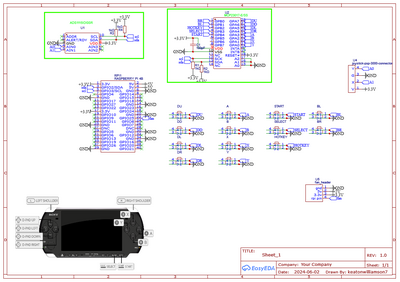
here is my Easy EDA sketch:
here are the data sheets:
thank you
Hi @tutelertundra76,
OK, thank you for your reply, which is a fair start, but please understand that you know more about your project than anyone else, so let's try to use the information you know.
You say, "I have tested this with modules before", which suggests you have built a working rig, albeit, maybe with a few different boards, wired together? But, I am only guessing, as I can't see your workbench.
However, if you have a working rig, that should be a rich source of information. So can I suggest you try to describe what you have, including photos, circuits, software? You may not have all of this information in a convenient form, but we can do it in stages.
So, for the first stage, perhaps you could provide an overview, and 2-3 photos, to get started. Include a summary of what works well, and which bits still need attention.
I hope that is clear. Best wishes, Dave
PS If your project is based on a published design, please provide a reference, as well a guide as to how your design is different. Thanks.
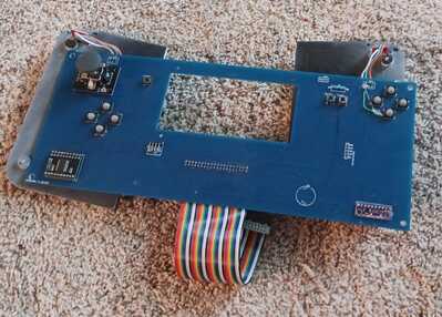
I am building a version 2 of this working controller I made using a guide by other mod
github: https://github.com/othermod/I2C-Linux-Gamepad-using-ADS1015-ADS1115-and-MCP23017
the green wire is to bridge the ground trace I messed up in design.
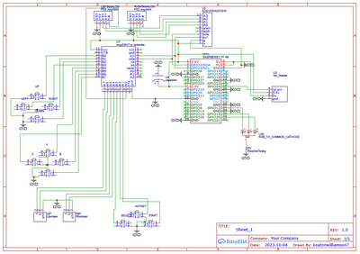
easy EDA schematic:
this design was my second ever PCB, and I made it quite big and hard to make a case for. this is why i have decided to make a V2. The modules are quite big so staying with the same wiring I would like to replace the modules for just the chips.
things that work well:all the buttons and the joystick
things that don't work well: it is quite big,the bumpers are annoying to mount
I plan to replace the modules with chips and get them preinstalled on the board. this will reduce the size and vertical height allowing me to mount it underneath the screen. The end goal is to make a raspberry pi 4 console about the size of a psp with a pi sugar ups and this controller .
thank you
I am building a version 2 of this working controller I made using a guide by other mod
[snipped
I plan to replace the modules with chips and get them preinstalled on the board. this will reduce the size and vertical height allowing me to mount it underneath the screen. The end goal is to make a raspberry pi 4 console about the size of a psp with a pi sugar ups and this controller .
So, just to be clear, it appears that you want us to help you reverse engineer proprietary modules so that you can include the minimal set of parts on your reproduction. I say that because if the components were in the public domain there'd probably be full schematics of the modules available online somewher and you wouldn't need to ask here.
Note also that it's unlikely that the Pi software would continue to work as expected unless you pretty much duplicated the original module's capability of transforming the signals to I2C.
Perhaps you can re-arrange your original PCB to reduce the overall size by making daughterboards much like hats for the Raspberry Pi. That may allow you to create a more acceptable form for a 3D printed enclosure by reducing the flat area by increasing depth.
Anything seems possible when you don't know what you're talking about.
@tutelertundra76 I assume you are looking for a smaller version of the MCP23017 I2C expander and a smaller version of the ADS1115 4 chan ADC.
A quick google shows several 'sizes' of both, pick one.
First computer 1959. Retired from my own computer company 2004.
Hardware - Expert in 1401, and 360, fairly knowledge in PC plus numerous MPU's and MCU's
Major Languages - Machine language, 360 Macro Assembler, Intel Assembler, PL/I and PL1, Pascal, Basic, C plus numerous job control and scripting languages.
My personal scorecard is now 1 PC hardware fix (circa 1982), 1 open source fix (at age 82), and 2 zero day bugs in a major OS.
Hi @tutelertundra76, Ron @zander and @will,
Thanks to all for your contributions. The aim of the project is now becoming clearer, which is a good start.
------------
Apologies, I have never used a gamepad, let alone built one, so please watch out for any mistakes.
--
Let's consider the items in decreasing space/volume requirements:
- The largest item of the project is the Raspberry Pi 4, whose dimensions are obviously fixed. I am guessing it will also have a display screen, which will sit over the top the R-Pi 4, and of a similar size.
- A joystick
- Two groups of 4 push buttons and about 3 other pushbuttons
- An ADS1115 4 channel ADC board
- A MCP23017 I2C expander board
There maybe one or two other components on what I assume is the front panel, which partly underneath the PCB in the photo.
Clearly the volume, etc. of the R-Pi 4, and any display, heatsink, fan, etc is not going to be amenable to change of size.
Similarly, the joystick and push button positions will be largely determined by the amount of space needed for human hands to operate them, which you can easily optimise, if required.
This leaves the ADC and the expander. It is difficult to see the detail of those boards in your photo, but the GitHub reference you supplied provides close-ups, which I assume look very similar to your boards.
The ADS1115 board appears to have:
- ADS1115
- 8-pin matrix resistor, pack 10k ... probably 4 independent resistors or 7 resistors with a common connection
- 2 brown capacitors
- 2 black capacitors [or resistors]
The MCP23017 appears to have:
- MCP23017
- 8-pin matrix resistor, pack 10kOhm ... probably 4 independent resistors [or 7 resistors with a common connection]
- 1 brown capacitor
- 2 black resistors .. maybe 10kOhm
Note, that since the existing boards are only a little larger than the components, and quite small compared to the R-Pi 4 and controls, although putting the same components directly on to your PCB could reduce the volume associated with the 0.1" board connections, the overall saving in 'floor area' will be quite modest.
---------------
So, now consult the data sheets, to try to ascertain the circuits of these boards, noting you have kindly provided copies of the datasheets above.
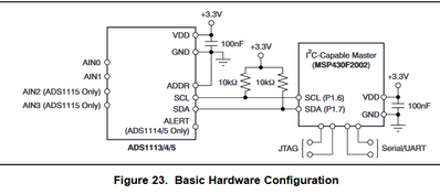
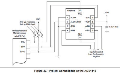
For the ADS1115, from the datasheet:
Clearly these diagrams are near copies of the same circuit, but they come from different parts of the datasheet, so I have included both as a reminder of the sections of descriptive text to consult, if we need further information.
Comparing these diagrams with the parts seen in the photos, it is probable that:
2. the matrix resistor is providing the pull ups needed for the two SDA lines, and possibly the Alert/Ready line as well.
One of the brown capacitors 3. is 0.1 microFarad, providing decoupling across 3.3V to Gnd, which must be located as close as possible to the chip.
This basically leaves, 4. the 2 black components, 1 brown capacitor, and possibly one or more 10k resistors in the matrix resistor pack unaccounted for. Most, or all, of these are probably acting as a simple low pass, input filter for the incoming voltages. If so, the values should be selected for the application, depending upon factors, such as, the amount of noise on the lines and sampling rate. With a multimeter to measure continuity, it should be easy to determine the circuit, and the only 'unknown' will be the capacitance values, for which you may wish to do some experimental testing. (Sorry, filter design is a whole course in its own right, so I can't describe it here.)
---------------
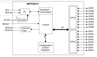
For the MCP23017, from the data sheet:
I couldn't see a 'typical' circuit in the sheet, so we have to try to understand the requirements, and match them to the visible parts.
There is only 1 capacitor, so that should be a decoupling capacitor, connected across the power input pins, and placed as close to those pins as possible. A value of 0.1 microFarad is a common choice for small logic chips.
The resistors are probably all providing pullups for the control pins, shown on the left ...SDA, SCL, A2:A0, INT A and INT B. You can check your board with a multimeter, looking for continuity.
I assume the output pins on the right of the diagram simply go to board connection pins.
---------------
For both of these boards, the manufacturer has only added a minimal number of extra parts to enable them to be used in a typical prototyping situation, mainly pull-ups for open drain outputs and configuration inputs, plus a decoupling capacitor for each chip. There may also be a simple RC filter on the Analogue-to-Digital Converter inputs.
I can understand that you might wish to simply copy the same circuit, if it works. However, I recommend you try to work through it, draw out the exact circuit, and then try to understand what each part is doing, as you may find it has duplicate parts, and/or some parts may not be optimal for your circuit. If you get a part of a circuit you don't understand, then consider asking another question.
For example, assuming the SDA and SCL connections from both boards go to the same pair of pins on the R-PI, then there will a pair of pull up resistors on each board, in parallel with another pair on the other board. In a 'properly designed' board, the SDA and SCL pull up values would be chosen for the characteristics of the circuit, including data rate, capacitance and inductance of the wiring, and so on. Whilst I doubt if this will be an issue in this case, if you progress into designing more complex systems, knowing how they work will become more important.
----------
So whilst, I haven't completely specified the circuit, I hope you now have enough guidance to look more carefully at your prototype, determine what you need, and produce a schematic that can be converted to a PCB layout.
----------
Of course, I appreciate @will's concern that this has bordered on reverse engineering a proprietary circuit, which raises ethical issues. If the question had been, how to make a copy of xxxx's game controller, where xxxx is a well-known, multi-national company, the position would have been different.
This question refers to two small boards, whose circuit design is almost predicated by the main chip in the middle, and whose physical construction suggests it is intended for quick prototyping, not a final product. They are clearly not even suitable for many amateur finished products, where the maker is concerned about factors such as space, reliability, wiring issues and so on.
In practice, chip manufacturers usually provide circuits in data sheets and application notes, as well as selling/issuing demonstration boards, encouraging engineers to design their chips into new designs, with circuits they can copy and adapt as necessary.
Many of the small boards now on sale at very low prices, including the two discussed above, are essentially extensions (and often copies) of this process, since they simply provide an easy to wire version of the basic chip. To use these parts safely and efficiently, it is actually a requirement that their design is well-understood. Ideally, the design would be well documented, as is demonstrated by companies like Adafruit. When the documentation is missing or inadequate, it is necessary to find out the information the hard way.
--------------
Best wishes to all and their projects, Dave
thank you all so much for your help

