Hi everyone!
I'm just new here and new to everything electronic, I just want to show what I have been working on, and I will probably need advice along the way, especially with code.
I have a few Ideas for producing robotics, but before I get to those I need to prove to myself that I can actually make them work, So the following project is to help me to learn how to code a robot to do the things that I need it to do. (hope that makes sense)
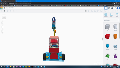
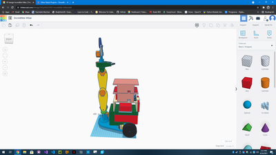
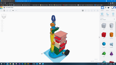
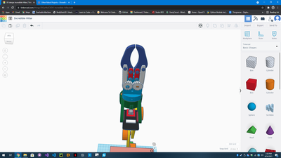
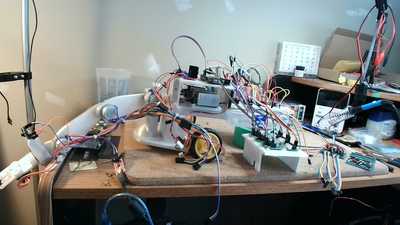
So in the first four images there are screen shots of my 3d design that I made on TinkerCAD, I am willing to share that file as soon as I figure out how, Although keep in mind that the battery is out of one of my cordless drills (Black&Decker 18V) and you will probably have to change the design to suit your needs.
Parts included so far:
B&D 18V Battery,
Small 120V on/off Switch,
Small bread board,
2x 5-30V to 1.25-30V DC Power Modules, (One outputs 5V, the other outputs 12V)
Elegoo UNO R3,
L298N MotorDrive Control Board,
2x 12v gearmotors and wheels,
6x 28BYJ-48 Stepper motors with Stepper Driver Boards,
ESP32 AI Thinker Cam,
Approx. 1 roll of PETG 3d printer filament
NUMEROUSE wires!!!
Comments about the build:
It is a fairly simple design that I came up with, Its not meant to be super strong or lift anything heavy and some parts I had from other kits or just parts I found around the house, although there are some parts that I specifically bought for this project.
Starting off with the battery it is labeled as an 18V battery but at full charge it is 20.7V, so the power comes from there and pos. (+) goes into a small 120V on/off Switch after that Switch I spliced 2 wires together, one for each of the DC Power modules, for the Neg. (-) side I simply spliced 2 wires together from the Battery to each of the Power Modules, these both have adjustable power outputs and fuses built in, Using my benchtop power supply and my voltage meter I adjusted one Power Module down to 5V to power all the components like the Arduino, ESP32, Shift Registers. The other Power Module I dialed down to 12V to power all the motors for wheels and steppers.
I wasn't sure about building my own power bar to distribute the power, so what I came up with was using the small prototyping bread board, and running the power from the Power Modules to the little breadboard, separating Neg. to one side, Pos. to the other side, 5V on the top area, 12V to the bottom area. The components all get plugged into the pin holes in the correct voltage, and as I run out of pinholes on one line I ad a jumper to the next line to ad more components, Seems to be working fine so far however I am not knowledgeable enough in this department, So if this is a mistake please let me know!
Next in line would be the ESP32 and the Arduino (Elegoo) UNO and I would like to talk about them both at the same time because my original plan was to have all the motor controls hooked up to the UNO and have each physical motor function as a programmed function (motor A forward, motor B backward, Stepper 1 clockwise, stepper 6 counter clockwise) then have the ESP32 do all the thinking and just serial communicate with the UNO all of the movement commands, I don't know if this is the correct way of doing that or not??
I have also considered that the ESP32 can also (I THINK) control all of the components, Obviously neither the UNO or the ESP32 have enough I/O pins to control all of these components on there own, So I bought a 30 pack of 74HC595 shift registers (10$ on Amazon, super cheap), GLAD I bought so many because I can get them to work fine in a breadboard but I think I'm cooking them as I solder them to a perf Board! Yeah I think I should have bought the soldering hats for them as well.... Anyway! So I'm learning about using Shift Registers and I understand how they work, but I'm looking for easier ways on using them with easier code. Im currently using the ShiftRegister74HC595 library in the Arduino IDE and it makes life pretty easy although I have not figured out how to adapt the Stepper library to work with the shift register pins, or the Motor library either. For testing the shift registers so far I have Used the previously mentioned Library and simply turned each pin to high and then set it back to low, and move on to the next pin and repeat the process, 24 times to make sure the shift registers are working in series and can run the 4 wires for each of the 6 steppers, using 3 Shift Registers, I also added a 4th Shift Register hoping I can run the 2 DC motors for the wheels, that is 6 connections I would like to take off the UNO, However I have no idea if that will work or not.
This brings me back to weather or not I even need the UNO if I can do all this from the ESP32? Is it better to have all the code on 1, or divide it up between the 2? I've also wondered if I could put a main code in an App and have it just send commands to the ESP32 via Bluetooth or Wi-Fi?
What I would like it to do:
Granted the arm is not expected to be terribly strong, However I believe it should be strong enough to pick up an empty beverage container. I would first like to use Dronebot Workshops tutorial and code from the robot car tutorial to make this robot remote control, the bigger picture is to write a program that will give this little robot the ability to recognize objects, Measure distance to an object, Plan a path to that object, Avoid obstacles on that path, Retrieve object, and place it in a desired location, and/or follow that object/person over distance.
So where am I at now:
Well its in pieces on my desk,
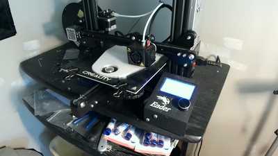
And I'm reprinting a new base because my balance was way off, so I made the base a bit longer and pushed the wheels back as far as I could, Its also hard to tell by my pictures but there is a ball and socket under the arm to take the weight on that side, granted balance may be an issue if you try lifting an object from the sides of the main body.
Problems I am running into:
I explained a lot about where I am having difficulties in the Comments about the build section, mainly in the coding end of things, but I am making steps forward.
I would love to hear your comments and advice on this project and as I figure out more I hope to share all of this project with designs and code to help others learn about robotics!
It looks very cool !
I don't know much about robots, but I'm very impressed that you can get enough usable power from the 28BYJ steppers.
The first step is to get it moving at all, then with speed and direction control. After that you can refine and expand the movements and sensors later.
Anything seems possible when you don't know what you're talking about.
@will Ya, that's what I was thinking, I have some 6 axis gyro sensors I thought would be cool to use and a whole bunch of other sensors to pick and choose from. just kind of experiment as I go. I also have a spot on it that holds a 3.5 inch touch display on the main body, that I included into the design but I really have no idea what it should display yet though. lol
I'm curious why you'd use a touch screen for a moving robot ?
Unless you plan to set a task when it's close to you, which task is completed only when it's close to you again (like "Hey Marge, bring me a beer").
Anything seems possible when you don't know what you're talking about.
@will Well to be honest I bought this Nextion touch screen and haven't found a project for it yet and decided that I will find some use for it on this robot. Part of me was hoping I could get the ESP32 to display its video feed to the screen, however I haven't found an example of that yet, so it may not be possible. If nothing else it helps someone to learn about graphical user interface.
I think it'd be a lot more useful to have the ESP32 cam display on your computer screen (and maybe be stored for later analysis). Displaying it on the robot's screen would be counter-productive since by turning your head slightly you could directly see what the camera saw.
It could be useful though in the future when you want to do image analysis (presumably live, onboard, maybe using a RPi or some other SBC) for more ambitious future projects.
I think you can do a lot of interesting things with the equipment you already have and having the extra grunt from that chunky 18V battery will give you a lot of leeway for future additions.
Anything seems possible when you don't know what you're talking about.
Should be a good learning experience for you 🙂
My only thought is perhaps the arm does not need such a long reach?
The reason I use a larger base is so I don't have to cram everything onto a small platform. The hardware is the same, there is just more room to play with.
Have you viewed this tutorial?
https://dronebotworkshop.com/esp32cam-robot-car/
@robotbuilder Thank you!
My main thought behind the arm was that the body could stay stationary while the arm with the camera on it, could look around or reach into a container. The over all size of the robot was limited by the size of my 3d printer as its bed is 220 mm by 220 mm and can only print 250 mm high, otherwise I would have made it bigger :), with my future robots I will be making those bigger with appropriately sized motors and better space for components, this one is just kind of a base to experiment with. I don't have much money so if I can get this one to work, then Ill sink some money into the bigger ones.
Yes that is the tutorial I was talking about in the description, sorry I think I called it something else....
@will Thank you
I agree with what you are saying about the esp32, I had imagined that I could some how display it on there as well as on my pc, It may just end up displaying the time and battery levels of possibly info from other sensors, I think that would kind of make sense?
Good to know about the battery, I probably know more than I think I know but I lack the confidence to be sure of myself! I like the fact it is rechargeable and I hope this little robot can run for awhile between charges with this battery.
@robotbuilder Thank you!
The over all size of the robot was limited by the size of my 3d printer as its bed is 220 mm by 220 mm and can only print 250 mm high, otherwise I would have made it bigger 🙂
If you keep the width/thickness small, you can print up to about 30 cm long pieces by printing diagonally (i.e. position your piece from corner across and up to the most remote corner. That's 22 cm times root 2 (appx 1.41).
The thing to watch for is that if you normally fill with diagonal lines, they'll come out parallel to the sides and will be less strong, so change the fill pattern to something else.
If you print the part with on it's side (i.e. the part is rotated so the part that rests on the build plate is the "height" and the "width" is printed vertical), you can build some pretty substantial pieces that are larger than the nominal size of the build plate.
Anything seems possible when you don't know what you're talking about.
@will Again, Thank you!
I will keep that in mind for further prints!
My main thought behind the arm was that the body could stay stationary while the arm with the camera on it, could look around or reach into a container.
Much like the eyes of an emu (ostrich) which use their beaks as hands 🙂
A long time ago I put a webcam on the elbow joint of a toy owi arm using a PC program controller with the same idea. Unlike the current toy owi arm the wrist rotated but did not bend while the latest "modern" flimsier version the wrist bends but does not rotate. The reality is that autonomously controlling an arm by vision alone is hard. The hard part is the vision processing along with an arm and hand limited by no feeling of touch, pressure or force feedback. You can manually remote control an arm to pick up objects but to do that autonomously is a whole different ball game.
I like the analogy of the ostrich or emu, yes Its very much like that! lol
Yes I agree this isn't going to be easy, and at first it will hopefully be remote controlled through the esp32 web server ( like Bill did in the video on the esp32 robot car) and I was planning to set the controls up like you would find in an excavator with a thumb attachment, not sure if you are familiar with those controls but it was one of the skills I picked up, and they are fairly intuitive.
I've got into a bit of using Open CV for computer vision in my projects, and although I have a long way to go, I've seen a lot of YouTube videos on vision control for robots and hope to employ this kind of tech in my robots and move into machine learning as I go to add some AI. I believe this is where the future is going and will need to keep up.
Never used an excavator myself but my first robot hand was sort of like that with two fixed fingers and a movable thumb. I used drill motors and threaded rods which would be like the linear action of the hydraulic pistons of an excavator.
So are you using Python with Open CV? I started so long ago I had to write my own visual processing algorithms. Because of the computing power required for a real robot I have always used a pc for a controller. The remote control simply being a wireless keyboard.

