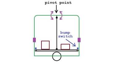
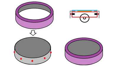
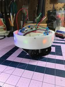
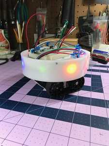
An idea I haven't actually tried was a shell (a bin upside down) sitting on a center pivot point that was free to "rock" when hitting something. It wouldn't even need to be circular. Sensors could have to be part of the shell or at least have windows or holes in the shell through which they could pulse sound or light.
The idea is you could just lift the shell off to work on the electronics. You could even have holes in it through which an arm could be attached.
Imagine it like this: get a rubbish bin large enough to fit yourself into. Cut a hole in the bottom so your head can fit through but small enough to sit on your shoulders. Two other holes for the arms.
To enlarge image, right click image and choose Open link in new window.
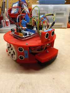
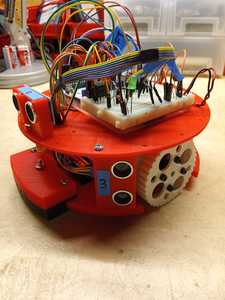
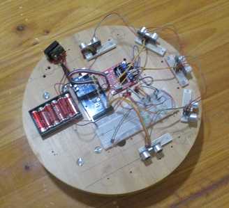
@robotbuilder If you are looking for ideas? Here are a few pictures of a round robot I built a few years ago. Uses Ultrasonic sensors for obstacle avoidance, and IR for the line follower on the front.
RCC1
Yes I have experimented with ultra sonic sensors.
To enlarge image, right click image and choose Open link in new window.
IR sensors can also be used for detecting a wall at a set of distances. Physical bumpers are just a fail safe over ride should the robot actually hit anything. Robot vacuum cleaners use a bumper but the more expensive ones depend on other sensors for navigation as well.
Reading up about the software used by robot vacuum cleaners I was interested to note that with two sensors on the bumper they can estimate an angle of collision by the time difference between each sensor registering a hit.
Just haven't got around to testing it yet but maybe monitoring the wheel encoders and/or current drawn by the motors may be used to detect a collision. If one or both wheel encoders stop sending pulses or the current increases dramatically then something has gone wrong.
Interesting idea for a bumper. You might have to dampen the movement somehow to avoid false positives when the robot starts and stops. Maybe a strip of some high density foam along the inside where the bumper makes contact with inside…
Reading up about the software used by robot vacuum cleaners I was interested to note that with two sensors on the bumper they can estimate an angle of collision by the time difference between each sensor registering a hit.
So robot vacuum cleaners use the different readings to predict an angle of contact. That’s an interesting tidbit. I noticed that Pololu is selling Lidar Time of Flight sensors that have an accuracy down to 1mm. Those could do the job!
Nice robot. Now you have to figure out how to add a bumper 😉
Tom
To err is human.
To really foul up, use a computer.
You might have to dampen the movement somehow to avoid false positives when the robot starts and stops.
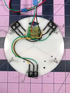
The only way to determine this is by trying it. If the switches have the right amount of spring tension they will act to hold the shell away by themselves and not react to weak pressure.
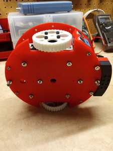
I actually found a light weight circular tray that fitted over my round robot base and cut out the bottom to make a bumper. I used large button switches but the switches internal springs didn't have the strength to reliably push the bumper back out again.
To enlarge image: Right click image and choose Open link in new window.
I never thought about using the switches to provide the force to center the bumper. I've always used piano wire. It holds the bumper in place and has some outward spring force to center it.
Can you lighten your tray/bumper? Is there some way to lessen the friction of the tray rubbing against the wooden base? Fewer points of contact? I'm reluctant to suggest compression springs for obvious reason. 😀
Tom
To err is human.
To really foul up, use a computer.
Putting the bumper on hold for the time being.
Here is a simple robot base.
https://cookierobotics.com/056/
If the base turns on the spot and otherwise only moves straight forward or a small backward step then a bumper that only wraps a little bit over half the circumference is sufficient (as in all round vacuum robots.
I don't have any woodworking tools apart from a little hand held wood saw and a hand held drill so I try and find off the shelf stuff like the round bamboo food tray I used as a shell for the above robot.
If the piano wire works that is all that counts.
Yesterday I got around to testing monitoring the wheel encoders for a collision using the number of pulses per second for a given PWM speed control value and it worked ok. I will order a couple of current (amp) sensors and try that out as well as that would be simpler.
Yesterday I got around to testing monitoring the wheel encoders for a collision using the number of pulses per second for a given PWM speed control value and it worked ok. I will order a couple of current (amp) sensors and try that out as well as that would be simpler.
Great news about the encoders. You’re putting to good use all of that research you did back in October. I really like using the data they provide. I’m using them in my latest project. I just wish that they didn’t take up so many pins! Two motor drivers and two wheel encoders take 8 pins minimum.
Tom
To err is human.
To really foul up, use a computer.
Yesterday I got around to testing monitoring the wheel encoders for a collision using the number of pulses per second for a given PWM speed control value and it worked ok.
Here is part of the test code. It uses experimentally determined encoder count values 700 which work with a fixed rate of 240 pwm to the motors. It enters the loop with the motors running when I press a start button. When it hits an obstacle (wall) it stops.
void loop()
{

  currentMillis = millis();  //total millisecond count since start

  if (currentMillis - startMillis >= period){  // if one second has passed

    if ( (counter1 < 700) || (counter2 < 700) ){
      turnOffMotorA();
      turnOffMotorB();
    }

    counter1 = 0;
    counter2 = 0;

    startMillis = currentMillis;   // reset timer
  }

}
I will order a couple of current (amp) sensors and try that out as well as that would be simpler.
acs712 30a current sensor
The sensors arrived but Jaycar only supplies the 30amp version. There is a 20amp and 5 amp version.
Using the code here to measure amps.
https://www.engineersgarage.com/acs712-current-sensor-with-arduino/
I wired them up in series with the motors and have started experimenting with the code.
Like the encoders above using them in a practical program is more involved than I thought.
Also using strain on the motors to detect an obstacle will probably shorten the life of the motors.
Although monitoring encoder and amp values will be useful to make sure everything is working properly a physical bumper is really the best choice as the primary obstacle contact sensor.
So a PWM setting of 240 gives you a duty-cycle/velocity that will run the encoder counts up to ~700 in one second. Right? When the robot is pushed up against something and the count is < 700 after a second you figure that you’re stuck… Hmm, interesting. You could put this in a subroutine that runs ‘escape’ behavior motor commands like backup, turn in place, resume forward speed.
I tried using motor current sensors on the Seeker robot's 12V motors, but I couldn't get it to work consistently. I was trying to figure out how I could determine if the robot was hung up on something. It's one thing to bump into the unseen chair leg and another to roll up on somthing that lifts a wheel up. With a bump I just backed it up, with a 'high side' I would do this crazy backwards waddle.
I'm with you on the idea that using a physical bumper to determine obstacle contact is the way to go.
Tom
To err is human.
To really foul up, use a computer.
@thrandell
You could put this in a subroutine that runs ‘escape’ behavior motor commands like backup, turn in place, resume forward speed.
Yep next step.
I tried using motor current sensors on the Seeker robot's 12V motors, but I couldn't get it to work consistently.
Ideas in the head work great but when you implement them for real issues arise 🙂
All goal seeking behavior is based on feedback. The sensory input (current state) is compared with the desired sensory input (goal state) in order to work out the next action.
I'm with you on the idea that using a physical bumper to determine obstacle contact is the way to go.
I am going to try your piano wire method to hold the bumper up until I think of something better.
Having someone to discuss these thing is a great motivator compared with those looking for high level packaged solutions using ROS.
I have written my own visual recognition algorithms for navigation although you could use RobotRealm software or something from OpenCV. More complicated to set up but without the need to understand how it all works at the lowest level. Working these things out and understanding how it works at the lowest level is the fun part for me.
https://forum.dronebotworkshop.com/user-robot-projects/robot-navigation/#post-17518
Working these things out and understanding how it works at the lowest level is the fun part for me.
Yeah, I'm the same way. I'd rather go my own way and learn from fellow roboticists like yourself then dive into a system like ROS.
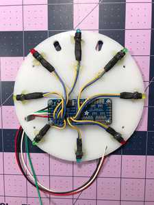
I want to move away from using LCDs and start using LEDs as the behavior level de-bugging interface on my latest robots. To test this out I added eight LEDs behind my usual white circular bumper, two each of red, blue, green and yellow.
I’m thinking of using patterns that use one color or all colors at once. With the PWM driver that I’m using I can control the brightness via the duty-cycle. So I could go with two intensities: dim or bright. And two transitions: smooth fade-up or a sharp on. That gives me 16 distinct single color LED patterns. I need to play with it to determine how long it takes to ‘read’ the interface.
Tom
To err is human.
To really foul up, use a computer.
I need to play with it to determine how long it takes to ‘read’ the interface.
Who, what is doing the reading?
It would seem to me the LCD is easiest for a human to read and without needing to learn a code.
You could use a LED to communicate between robots like the IR remote controls. A robot could send its ID and the ID of the robot it is sending a message to and then wait for a reply from the other robot.
https://dronebotworkshop.com/using-ir-remote-controls-with-arduino/
I have experimented with the nrf24l01 for a radio link between two laptops but it could also be used to link a laptop and robot or even link two robots. I posted about it recently.
https://forum.dronebotworkshop.com/introductions/my-first-time-creating-a-wecome-post/#post-28213
And some time ago.
https://forum.dronebotworkshop.com/introductions/hello-everybody-rclawn-arduino-robot-car-with-nrf24l01/paged/4/
As you know from past discussions, I love the theory of robotics and artificial intelligence, but what I find most frustrating is that there is (not to my current knowledge or awareness at least), no real consensus on the best way to implement a robotic algorithm, nor even the best communication protocol to use (I2C, CAN BUS, SPI, etc...), a streaming set of instructions, let alone a static set of predefined instructions via a file or serial communication for example, and then there is intelligence logic and programming on top of that!
When most people here talk about robotics, they never really define what kind of robot they would like to build, how and why, and for what purpose.
There should (IMO) be a dedicated forum (Bill?), for this topic (for example: common robotic algorithms), because it is a quite an advanced topic for advanced users to be sure 🙂
Cheers
PS:
At the sake of sounding like: "Vinnie Barbarrino": "What, When, Where!"
😉
I need to play with it to determine how long it takes to ‘read’ the interface.
Who, what is doing the reading?
It would seem to me the LCD is easiest for a human to read and without needing to learn a code.
You could use a LED to communicate between robots like the IR remote controls. A robot could send its ID and the ID of the robot it is sending a message to and then wait for a reply from the other robot.
https://dronebotworkshop.com/using-ir-remote-controls-with-arduino/
I have experimented with the nrf24l01 for a radio link between two laptops but it could also be used to link a laptop and robot or even link two robots. I posted about it recently.
https://forum.dronebotworkshop.com/introductions/my-first-time-creating-a-wecome-post/#post-28213
And some time ago.
https://forum.dronebotworkshop.com/introductions/hello-everybody-rclawn-arduino-robot-car-with-nrf24l01/paged/4/
My intension was not to de-rail your topic. I just thought this was an interesting example of a hybrid of Mechanical Bumpers and the Human-Robot interface. Maybe there should be a new topic on the forum for Human-Robot interface design.
For what it’s worth, my current interest is in using multiple (10 or more) autonomous robots in a controlled (bounded) environment. So from that perspective I’ve already considered your suggestions of LCDs and radio to laptop and rejected them because I don’t think that they will scale. I can elaborate but like I said before I don’t want to de-rail this topic.
Tom
To err is human.
To really foul up, use a computer.

