First a heads up! I am a self taught hobbyist not a certified expert on electronics or programming.
Some years ago I experimented using motor encoders to drive an Arduino based robot base in a straight line along a fixed distance, stop and turn 90 degrees. Do that four times to complete a rectangular path ending up at the same position and pointing in the same direction in which it began. It seemed to work with some error which I put down to trying to keep the motors synchronized. I was never aware the encoder count did not correspond to the wheel encoder's spaces until I returned to try and use the encoders for some dead reckoning odometry experiments and actually opened the casing to see the encoder itself.
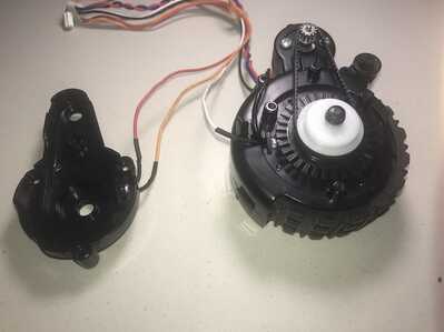
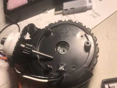
This is the motorized wheel with encoder I used. It was scavenged from a robot vacuum cleaner.
To enlarge an image, right click image and choose Open link in new window.
The encoder wheel is attached to the wheel axel rather than the motor so I figured it should produce 32 pulses per one wheel rotation.
However in practice the software required a count of 743 pulses per wheel rotation! (see source code) Despite the fact that when I manually and carefully turned a wheel very slowly the output seemed to click the output indicator LED on and off cleanly. Maybe there is noise somewhere. I don't have an oscilloscope to check.
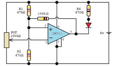
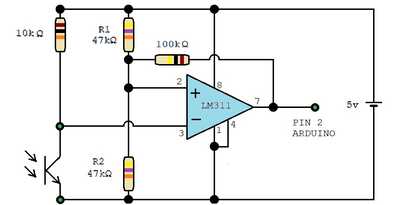
I only had LM311 comparators at the time and this is the Schmitt trigger circuit I used.
https://en.f-alpha.net/electronics/integrated-circuits/comparator/lets-go/experiment-9-inverting-schmitt-trigger/
Surely I should be able to read exactly 32 pulses per wheel rotation! The 743 pulses required for one wheel rotation must be due to a lot of noise that averages to a similar count for each wheel rotation. This averaging was probably why my earlier experiments seemed to work but with some error.
At this stage I am not sure what to do next.
Code to rotate a wheel once every time a button is pressed.
// Motor A
int enA = 11;
int in1 = 10;
int in2 = 9;
// Motor B
int in3 = 7;
int in4 = 6;
int enB = 5;

int counter1 = 0;
int counter2 = 0;

// button pins assignments
const int btn0 = 4;        // press button purple
const int btn1 = 3;        // state of encoder1 green
const int btn2 = 2;        // state of encoder2 yellow

void forwardA(int rate){
  digitalWrite(in1, HIGH);
  digitalWrite(in2, LOW);
  analogWrite(enA, rate);
}

void forwardB(int rate){
  digitalWrite(in3, HIGH);
  digitalWrite(in4, LOW);
  analogWrite(enB, rate);
}

void reverseA(int rate){
  digitalWrite(in1, LOW);
  digitalWrite(in2, HIGH);
  analogWrite(enA, rate);
}

void reverseB(int rate){
  digitalWrite(in3, LOW);
  digitalWrite(in4, HIGH);
  analogWrite(enB, rate);
}

void turnOffMotorA(){
  digitalWrite(in1, LOW);
  digitalWrite(in2, LOW);
}

void turnOffMotorB(){
  digitalWrite(in3, LOW);
  digitalWrite(in4, LOW);
}


void setup()
{

  // Set all the motor control pins to outputs

  pinMode(enA, OUTPUT);
  pinMode(enB, OUTPUT);
  pinMode(in1, OUTPUT);
  pinMode(in2, OUTPUT);
  pinMode(in3, OUTPUT);
  pinMode(in4, OUTPUT);

   pinMode(btn0,INPUT_PULLUP);

  pinMode(3,INPUT); // set as input
  digitalWrite(3,HIGH); // enable internal pullup resister
  attachInterrupt(digitalPinToInterrupt(3), encoder1, RISING); // interrupt initialization

  pinMode(2,INPUT); // set as input
  digitalWrite(2,HIGH); // enable internal pullup resister
  attachInterrupt(digitalPinToInterrupt(2), encoder2, RISING); // interrupt initialization


  counter1 = 0;
  counter2 = 0;

  Serial.begin( 9600 );
  Serial.println("Starting up");

}

// interrrupt server routines for reading encoder

void encoder1()
{
  counter1 = counter1 + 1;
}

void encoder2()
{
  counter2 = counter2 + 1;
}


void loop()
{

  if (!digitalRead(btn0)){   // if button is pressed start motors
    forwardA(200);
    forwardB(200);

    counter1 = 0;
    counter2 = 0;

    while (counter1 < 743){    // this will result in one wheel rotation
      Serial.print(counter1);
      Serial.print("  ");
      Serial.println(counter2);
    }

    turnOffMotorA();
    turnOffMotorB();

  }
}
I give a link to a good write up on using encoders. The code examples are in micropython, but as I know you can do python I think you will get some good tips. But its more for the coverage of the subject matter that I think the article may be of interest to you.
I dont know if you have a rpi pico, but if so then the code example offered up may be relevant. This uses the PIO state machine and the the Viper Code means the python is complied direct to machine code for very fast execution.
Quote: 3) encoder_rp2.py Version specific to Raspberry Pico RP2 chip. This uses the PIO and Viper code to achieve fast response - upto ~10K transitions/s.
https://github.com/peterhinch/micropython-samples/blob/master/encoders/ENCODERS.md
Hi @robotbuilder,
I have only glanced at this thread, and not looked at the software code, but from your description, from whodunnit point of view, the alibis from your hardware do not add up.
If the encoder is attached to the wheel has 32 pulses/rev, that is 1 pulse per 11.25 degrees. So using a combination of the LED which shows the Schmitt output, a cutdown of your software to just one encoder, and no motors, but printing out something everytime the input changes, and some careful manual slow rotation of the wheel you should be able to see it count each pulse, with an eyeball correlation between the LED and the printouts.
For the software printing, maybe choose a '-' for off, and a '+' for on, no carriage returns/line feeds and high serial monitor data rate to minimise time taken to print.
As you have already realised, this is one of those occasions an oscilloscope can be really handy, but I think there are things we can try without one.
--------
My first guess, which like all good whodunnits is usually the obvious but wrong suspect, is lack of decoupling. Certainly, the lack of decoupling is asking for trouble, and should be rectified. (I am disappointed the author of the article you referenced didn't mention it.)
The optimal values for decouplers is something of a mixture of science, art and luck, as there are a lot dependencies, but I would start off with a pair of capacitors, say 100 uF (microFarad) and 0.1 uF in parallel with each other, and connected in parallel with the battery, but as physically close, and with leads as short as possible to the power input pins of the comparator.
As you have two comparators, then do the same for the other comparator.
The exact values of the capacitors are not that critical, so use what you have in spares box. The idea is that when the comparator changes state, it will take a quick, but large 'slurp' of current. The inductance and resistance associated with the wiring and battery will impede the current 'slurp', causing a voltage drop, so that the volatge across the chip will be less than the 'steady state'. Furthermore, the 'ground' reference voltage will move, so that the input voltage, with respect to ground, that the comparator sees, will be different. If the voltage change is large enough, it may cause the comparator to 'change its mind' as to which side of a threshold the input is, resulting in multiple transitions at the output, for a single 'intended' transition at the input. The capacitors act a bit like a tiny 'battery' or charge reservoir, to provide a quick boost of current when the demand is spikes high, and being connected by short leads, are less affected by wiring inductance.
The capacitors mentioned are 0.1 uF, usually ceramic, which is better at 'medium' frequncies, and 100 uF which holds more charge, for a 'sustained' supply, but they become less effective as the frequency rises. For higher speed logic circuits, I would suggest a third 0.01 uF in parallel as well, to further increase the frequency range, and might even be helpful here.
(Don't forget the electrolytic is polarised and must be connected the right way round!)
It is feasible, that by having two comparators on the same battery feed, but no decoupling, that a change on one comparator was also causing the other one to change. Hopefully, adding decouplers will fix that possibility.
Best wishes and good luck, Dave
@davee @robotbuilder Or just switch to stepper motors, so much easier to control.
First computer 1959. Retired from my own computer company 2004.
Hardware - Expert in 1401, and 360, fairly knowledge in PC plus numerous MPU's and MCU's
Major Languages - Machine language, 360 Macro Assembler, Intel Assembler, PL/I and PL1, Pascal, Basic, C plus numerous job control and scripting languages.
Sure you can learn to be a programmer, it will take the same amount of time for me to learn to be a Doctor.
I do have a rpi pico somewhere. I also have a nice little RPi computer setup to play with. However it would be used as a higher level controller that communicates with an Arduino. I actually like low level stuff as Assembler and hardware was where I first started my hobby back in ye olden days.
I had thought of increasing the speed of the Arduino i/o by directly changing the ports rather then using things like digitalRead() although I also seem to recall that such low level code might need to be modified for different boards. Maybe there are different versions of things like digitalRead() depending on what board you are using.
Thanks for the link I found it an interesting read.
Yes I did think about the Serial.print as perhaps an issue and tried a higher monitor data rate. I have just found out that I should turn off interrupts when printing.
cli();
int temp = encoder1;
Serial.print(temp);
int temp = encoder2;
Serial.print(" ");
Serial.print(temp);
sei();
Rather than print the data on the run I might store it and then turn on printing the results for inspection later.
I did think of decoupling. I added a small capacitor between the schmitt output and the ground. The power source of the motors is separate from the 5 volt power source used by the Mega and the schmitt cct.
I notice the pin in the interrupt routine can be set up for RISING or FALLING not for crossing a threshold. So I can imagine a small up or down could be seen as a signal. I have played with software solutions with better results rather than using a hardware interrupt.
I choose to get this thing working, not because it is easy, but because it is hard 🙂
Actually I didn't think it would be hard. I read it being used without any mention of the issues I struck. However I have recently found on the Arduino forum some have had issues. In fact two years or more ago I thought I had got it working as the dead reckoning seemed to be working. I may have been getting the wrong number of pulses but they were consistently wrong. The 743 pulses I am getting do result in a complete rotation of the wheel.
A small stepper motor robot would be fun to build but I just don't think I will have the time. My main real interest has always been how thinking machines work, including the one between our ears. So I tend to think about AI programs. I would love to have a clearer understanding of OpenAI technology and have been reading a lot about it.
Hi @robotbuilder,
re:
I added a small capacitor between the schmitt output and the ground.
I should like to clarify that a capacitor on the 'data' signals like the Schmitt outut and ground is not decoupling ... it might act as a low pass filter, although depending on the impedance of the output stage versus the effective reactance of the capacitor, it may or may not have an appreciable effect.
However, decoupling capacitors are connected across the power supply connections.. they act like little local power reservoirs.
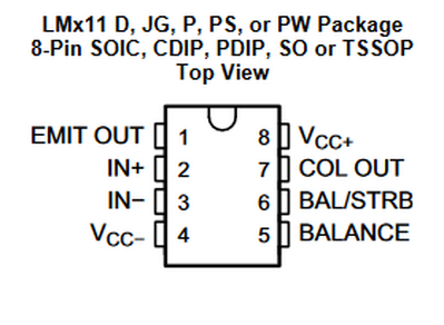
From the data sheet: https://www.ti.com/lit/ds/symlink/lm311.pdf
So the decoupling capacitors I described should be connected from pin 4 to pin 8, with wires as short as possible, and with the positive terminal of the electrolytic capacitor connected to pin 8.
--------
I have also just noticed this comparator is a little more complex than a 'minimal' device, but the only circuit you have provided is a demonstrator of the principle, rather than a useful complete circuit.
I recommend you post the actual circuit you have built, in case there is a hidden issue.
Whilst interrupts can be helpful, initially I would aim to use the simplest code, even if it is very speed limited.
Something that produces about 740 pulses instead of 32 for a single rotation is clearly fundamentally confused, and I think the best starting place is to ensure that the hardware is doing its job properly.
Best wishes, Dave
Hi @davee
Now I feel a bit silly. It has been over 30 years since I really did any electronics. Here I am talking about a threshold value when it is about a hysteresis zone. When I saw the use of a LM393 in an encoder module I thought it was the Schmitt trigger and maybe a LM311 would be a substitute. But it is a comparator, a component you can use in a Schmitt trigger circuit.
https://en.wikipedia.org/wiki/Schmitt_trigger
I wonder if I can use a 74xx14 hex Schmitt inverter?
Hi @davee
Thanks for pushing me in the right direction. I have spent some time finding tutorials on designing a Schmitt trigger circuit using a comparator and also one on using a 74HC14 so hopefully I will get something working properly.
Hi @robotbuilder,
No reason to feel silly .. well done for trying and investigating! If you follow someone's 'recipe' and it all works first time, you are entitled to a feeling of achievement, but maybe didn't learn much.
If you have a small 'technological campaign' with some project, lose a few battles on the way, but succeed in the end, you will probably have learnt a lot, particularly from the battles that didn't go your way first time.
My first concern (after lack of decoupling) is that I don't what voltages your encoder is putting out.
Obviously a 'scope would be convenient, but a voltmeter and some patience might be enough.
With the sensor side powered on, try attaching a voltmeter to the output of the encoder, and very slowly rotate the wheel by hand, looking for the highest and lowest voltages, corresponding to the photodetector seeing the most and least light (or vice versa).
This will give some idea of signal voltages a comparator or similar circuit will need to deal with. You might like to report them back to the forum to see if it provokes any useful suggestions.
Best wishes and keep going, Dave
ps a 74hc14 is simpler, though theoretically less 'flexible', to deal with than the comparator you mentioned, but logic chips like 74hc14s, and even other things like amplifiers also need decoupling capacitors. 😉
I didn't recall the term decoupling capacitor but I do understand the function of a capacitor across the terminals of a voltage source in ac circuits. I was thinking you meant to use it to earth out high frequency variations at the circuit output.
I haven't figured out why I am not getting 32 pulses per wheel rotation yes!
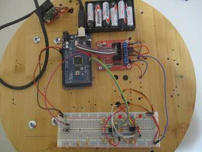
Here is my wiring up of the Schmitt circuit from the online link above.
To enlarge an image, right click image and select Open link in new window.
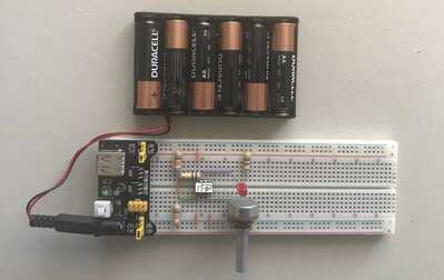
Here is a bread board of the circuit which I used to test the upper and lower threshold using a volt meter.
The LED turned on when the input voltage reached 2.64 volts. The LED turned off when that was lowered to 2.12 volts.
I thought this was a good introduction to the math involved.
Here is my modification for connecting the encoder to the Arduino.
Hi @robotbuilder,
Whilst the underlying science principles are the same, it is simpler to imagine capacitors that are providing the decoupling function are doing a different job from those acting as a low pass filter.
The decoupling job is about providing a circuit, or part of a circuit, such as an integrated circuit (IC), with an improved power supply. e.g. If a circuit is powered by a new, 5V battery, and the wires from that battery go straight to pins of an IC, then you might expect that the IC will see a steady 5 volts at its connected pins.
However, most useful circuits continually change the current demand ... in the case of your comparator, the voltage from your light detector will vary as the amount of light is changed, and that in turn will change the current demand by the comparator from its supply, the battery.
The battery itself is not a 'perfect' 5V source .. if you measure the voltage, when it is connected to a variable load, you will find that as the current draw by the load increases, the voltage at the battery terminal decreases. This is usually described in terms of 'internal resistance' of the battery. That is, we imagine the battery contains both a 'perfect' voltage generator of (say) 5V and a resistor in series. Hence, if we measure the voltage without drawing any current, the voltage will be 5V, but if we start to draw any current, then some of the 5V will be dropped across this 'internal resistor'.
In addition to the internal resistance of the battery, the connection between the battery and the comparator uses wires (and maybe PCB tracks or conductors inside the breadboard, etc.). These wires all have a small resistance and small inductance of their own, which when a current passes through them, will also result in voltage drops.
Now the 'steady state' current draw of reasonable comparator is low, so the voltage drops across these various intrinsic resistors and inductors will similarly be very small ... probably far too small to measure with 'affordable' test gear. But, when the comparator flips from one state into the other, it may take a surprisingly large current for a very small time ... the current flows can amount to Amps, albeit for a period of less than a microsecond ... and this can cause the voltage 'seen' by the comparator. This voltage change can be enough for the comparator to 'change its mind' about which state it should be in ... and hence a single transition can turn in to several transitions or can 'lose' the first transition.
To minimise the voltage change of the incoming power 'seen' at the IC power input pins, one (or more) capacitors can be connected with very short wires to those IC pins, to act as a 'charge reservoir' and help to keep the voltage steady, in spite of the rapidly changing current demands of the IC.
I am sure there are lots of explanations on the web on the topic. e.g.
Wikipedia's effort is a bit dry, but includes photos etc. showing examples, so is worth a glance: https://en.wikipedia.org/wiki/Decoupling_capacitor
This blog is saying the same as I am aiming to say: https://www.autodesk.com/products/fusion-360/blog/what-are-decoupling-capacitors/
This article starts to discuss the difference between decoupling and filtering:
https://learn.sparkfun.com/tutorials/capacitors/application-examples
---------
Looking at the last circuit diagram you have provided, then apart from the lack of decoupling capacitor, which I assume you will now fix, the next concern is the the lack of a pull up resistor on the output of the comparator. The 'ideal' comparator in the YouTube explanation had 'perfect' pull up and 'pull down' characteristics. When you had the LED in the circuit, that would have acted as a pull up, though the output voltage rise would probably not have been cleanly defined because of the voltage drop characteristics of the LED, which could have confused the Arduino.
The output of this particular device, unlike the majority of logic devices, is both 'open collector' and 'open emitter'. On your circuit, pin 1 is connected to ground, which deals with the 'open emitter' concern, but not the 'open collector'. Hence, if the output transistor turns 'on' , it can pull the output to near 0V, but the chip relies on the external circuit to pull it to near the supply rail when the transistor is turned off.
In your circuit, there is only a high impedance path via a 100K & 47k Ohms resistor chain, which is not designed or suitable for that job, and whatever the Arduino input does, which if "Input Pullup" is chosen is likely to be between 20k and 50k Ohms, which is also unsuitable.
Hence, I think I would start by adding a resistor .. maybe 1k Ohm, between pin 7 and the 5V supply rail. I would take out the LED to avoid the risk of it confusing the Arduino.
Then, using a voltmeter connected to pin 7 and ground (pin 4) to measure the output, assuming the encoder light source is powered, try very slowly rotating the wheel/encoder disc and try to measure the voltage in the two output states ... they should be near to 5V, and 'fairly near' to 0V ... say 0.6V.
If you cannot find these two states, then move the voltmeter probe from pin 7 to pin 3, and look for the maximum and minimum voltage. Also measure the voltage range pin 2.
Then provide an update of your findings here.
Good luck. Dave
Hi @davee
I was just unaware or forgot when a capacitor was used that way it was called a decoupling capacitor.
As I wrote at the start of the other post I do understand, and have always understood, the function of a capacitor being used to maintain a voltage level much like a car suspension evens out the bumps in the road or just as a home water pressure booster is used to provide a constant water flow when extra taps are turned on and off.
A battery can be seen as an ideal constant voltage source in series with an internal resistance.
One of the problems with explaining stuff is not knowing the current state of knowledge of the person you are talking to particularly in my case where there are big gaps in my knowledge due to being self taught and that was a long time ago. Since then I haven't done much electronic stuff as my interest was more into AI which involved software not hardware.
The Arduino provides the resister for the comparator's output collector .
pinMode(2,INPUT); // set as input
digitalWrite(2,HIGH); // enable internal pullup resister
attachInterrupt(digitalPinToInterrupt(2), encoder2, RISING); // interrupt initialization
Another problem with trying to help others on the forum is knowing what questions to ask when you are not actually there to look and check yourself as the questioner may have failed to mention something important. You might have done what I just did, observe the on/off flashes happened with a very slight manual movement of the wheel despite the encoder only having 32 slots!
It occurred to me that the electronics in the encoder may be more complex than I thought with more than one IR detector. However when I removed the casing and tried turning the wheel I saw the encoder rotating faster then the wheel. So I lifted the slotted disc off to discover it was connected to the main shaft with planetary gearing! Counting the difference indicated a ratio of 25:1 in other words 25x32 which equals 800 pulses per rotation.
So one major step toward resolving this issue. These exchanges helped motivate me to keep working at it so thanks for your interest.
To enlarge an image, right click image and select Open link in new window.
@robotbuilder I am not sure why you do it this way,
pinMode(2,INPUT); // set as input
digitalWrite(2,HIGH); // enable internal pullup resister
attachInterrupt(digitalPinToInterrupt(2), encoder2, RISING); // interrupt initialization
isn't the normal way
pinMode(2,INPUT_PULLUP); // set as input and enable internal pullup resistor
// needed ??? digitalWrite(2,HIGH);
attachInterrupt(digitalPinToInterrupt(2), encoder2, RISING); // interrupt initialization
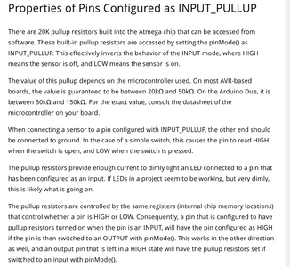
According to the Arduino.cc that was a very old technique prior to 1.0.1. See pic
Now there is a pinmode of INPUT_PULLUP, see pic.
The following links are to the arduino.cc docs for further details LINK1 and LINK2
First computer 1959. Retired from my own computer company 2004.
Hardware - Expert in 1401, and 360, fairly knowledge in PC plus numerous MPU's and MCU's
Major Languages - Machine language, 360 Macro Assembler, Intel Assembler, PL/I and PL1, Pascal, Basic, C plus numerous job control and scripting languages.
Sure you can learn to be a programmer, it will take the same amount of time for me to learn to be a Doctor.

