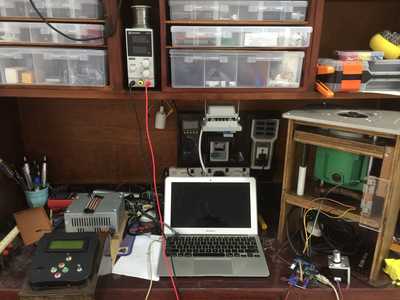
@sean451 ...and you are using the evil breadboard power supply!
"Hardware eventually fails. Software eventually works." - Michael Hartung
@theoutlander Yup, it's an Elegoo that came in the Arduino kit and set to 3.3v. Next I'll experiment with making the lights do fun stuff with my micro-controllers.
--->Sean
(◕(' 人 ') ◕)
Today's experiments were done using the Raspberry Pi Pico with the Pico Explorer that arrived the other day. I haven't done much with the display yet, but I did manage to get the led to work with the PWM pins. At least, I think I did.
Cheers!
--->Sean
(◕(' 人 ') ◕)
Nothing on my bench today. Since I don't have a dedicated space for hobbies, as of now. 🤔
However today I just received a Raspberry Pi 3B+, the official 7" touchscreen and a case for them in the mail today, so that will be my project to get that up and running the next few days.
It will run Node Red and a MQTT broker to start with.
Take a look at the IOTstack that has been mentioned elsewhere on the forum. It includes the MQTT broker (Mosquitto) and Node Red as well as InfluxDB and Grafana.
Just got that installed myself on a RasPi 4 and having a blast playing with an ESP32 just measuring temperature and humidity at the moment but writing the data to a database and then displaying graphically that data.
Welcome to the forum.
SteveG
@codecage Thank you for the tip and the welcome. I will have a look.
I'm not familiar with InfluxDB, but was thinking about using an SQLite database. It's only a 1GB model after all and I'm not really knowledgeable on the resource usage of the PI.
However if I run a webserver on a Debian'esqe 1GB server in the cloud, it can do quite a bit. I will likely make my own web interface in Vue.js, which calls into node red and other services and servers. As I understand it, it's easy making HTTP endpoints.
But it will have to wait until tomorrow, because someone can't seem to find any MicroSD cards around the place and shops are closed.
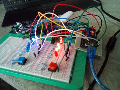
I was inspired by the LED Dice Project on the Arduino site and wanted to expand the program to work for two six-sided dice. After much programming and wiring and a definite Eureaka! moment (I realized why the program needed the I/O pins to be in consecutive order), I succeeded in creating a prototype.
Note that the blue button is not connected to anything, it was just there to check that the blue dice worked with the pins I chose. Also, everything is connected to the Arduino mega, the Uno is just there on the breadboard holder.
So now the next logical step is to shrink the project and make it portable. I've got some AtMega modules (both 5v and 3.3v--thanks for the video Bill!) coming in today that I want to use. My question is there enough I/O pins that I can use? Each die uses six pins and the button another pin and a single connection to GND and the 5v on the Mega. Info on the module says there's 14 digital I/O pins available. Would that be enough for this project? I'm planning on experimenting with an Arduino Nano while I wait for the AtMegas.
Cheers!
--->Sean
ETA: The program worked fine on the Nano. I wired the dice LEDs to pins D2 through D13 and the button to analog pin A0 which in the sketch was defined as pin 14. Next stop...AtMega328.
(◕(' 人 ') ◕)
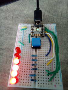
Yet another iteration of my six sided dice project. This one uses Pimoroni's Tiny2040 module. I used Thonny and modified the Arduino sketch, but I haven't figured out how to turn the pins off and on within a for or while loop. If anyone has any idea how to do this, I'd be grateful. I'm still learning Micropython and I don't think much has been done with machine pins and iterations which was quite simple in Arduino.
# LED Single Dice on Tiny2040

# Circuit:
# Six LEDs +ve connected to six 220Ω Resistors to Pins 1-6 -ve to GND.
# Touch switch connected to Pin 26 (Analog A0) and PWR rail.
# Tiny2040 5v (0) and Ground (1) to PWR and GND rails.


# Imports

import machine, utime, random

# Declarations

timer = .05                           # Delay timer to flash LEDs
hold = 2                              # Delay timer to pause dice roll

pip1 = machine.Pin(1, machine.Pin.OUT)
pip2 = machine.Pin(2, machine.Pin.OUT)
pip3 = machine.Pin(3, machine.Pin.OUT)
pip4 = machine.Pin(4, machine.Pin.OUT)
pip5 = machine.Pin(5, machine.Pin.OUT)
pip6 = machine.Pin(6, machine.Pin.OUT)

button = machine.Pin(26, machine.Pin.IN, machine.Pin.PULL_DOWN)

# Functions

def flashPips(): # Turn each LED on & off
    pip1.value(1)
    utime.sleep(timer)
    pip2.value(1)
    utime.sleep(timer)
    pip3.value(1)
    utime.sleep(timer)
    pip4.value(1)
    utime.sleep(timer)
    pip5.value(1)
    utime.sleep(timer)
    pip6.value(1)
    utime.sleep(timer)
    pip6.value(0)
    utime.sleep(timer)
    pip5.value(0)
    utime.sleep(timer)
    pip4.value(0)
    utime.sleep(timer)
    pip3.value(0)
    utime.sleep(timer)
    pip2.value(0)
    utime.sleep(timer)
    pip1.value(0)
    utime.sleep(timer)

def flashRoll(): # Function to display random die roll.
    pip1.value(1)
    if (ran >= 2):
        pip2.value(1)
    if (ran >= 3):
        pip3.value(1)
    if (ran >= 4):
        pip4.value(1)
    if (ran >= 5):
        pip5.value(1)
    if (ran == 6):
        pip6.value(1)

# Loop

while True:
    ran = random.randint(1, 6)
    if button.value() == 1:
        flashPips()
        flashRoll()
        utime.sleep(hold)
        flashPips()
Cheers!
--->Sean
(◕(' 人 ') ◕)
I haven't figured out how to turn the pins off and on within a for or while loop.
Hey, if you can do it in Arduino code then you can do it in micropython. 😀
Are you meaning you want to continually flash the led's on and off whilst waiting for your button to be pressed? I'm not clear what you want.
Maybe you want the following
while True:
ran = random.randint(1, 6)
if button.value() == 1:
flashPips()
flashRoll()
utime.sleep(hold)
flashPips()
Note the unindented flashPips() or maybe you just need an extra flashPips() after your if code block. Either way that would make your flashPips() function to get called on each while loop, only to get a brief interlude for extra code to run if your button.value() was True.
@byron In the Sketch, it would first set the pins to OUTPUT using a for loop:
   for (int i=pip1; i<=pip6; i++) {
    pinMode(i, OUTPUT);
  }
But that's done in the declaration, so it's not necessary here. In the flashPips() function, it does this:
void flashPips() {
  for (int i=pip1; i<=pip6; i++) {
    if (i!=pip1) {
      digitalWrite(i-1, LOW);
    }
    digitalWrite(i, HIGH);
    delay(100);
  }
  // right to left
  for (int i=pip6; i>=pip1; i--) {
    if (i!=pip6) {
      digitalWrite(i+1, LOW);
    }
    digitalWrite(i, HIGH);
    delay(100);
  }
}
That certainly looks more efficient that what I've got. I've been trying to do the same thing with Mircropython with not much success, but that's how I learn.
Cheers!
--->Sean
(◕(' 人 ') ◕)
Im with you now, have a look at the following:
import machine
import utime
LED_pin_number = [1,2,3,4,5,25]
for pin in LED_pin_number:
machine.Pin(pin, machine.Pin.OUT)
def flash_all_my_pins():
for x in range(0,6): # Lists start with 0 and the range starts with 0 and stops at 6 (so 0-5 for 6 pin #)
LED = machine.Pin(LED_pin_number[x])
LED.toggle()
utime.sleep(0.2)
while True:
flash_all_my_pins()
# and then carry on looping
Note I put pin 25 in my 'list' as its the onboard Pico LED, amend the list for the pin number you have attached your LED's to.
if you were just using pins 1 to 6 then here is another thought on initialising the pins to output and then have them all flash. I know your code requires more to roll the dice etc, but I thought this additional example may help.
import machine
import utime

LED_pins = []

for x in range(1,7):
    LED_pins.append(machine.Pin(x, machine.Pin.OUT))


def flash_all_my_pins():
    for pin in LED_pins:
        pin.toggle()
        utime.sleep(0.2)


while True:
    flash_all_my_pins()
    # and then loop again.
(◕(' 人 ') ◕)


