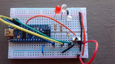
I'm in the middle of Build an ESP32CAM Robot Car but realized I needed to practice some beginner skills first. I wanted to do a very small project, that is, a perfboard, that did a little something, but mainly helped me practice arranging components, planning the soldering, etc. Based on a tutorial I saw, I built it first as an "experiment," i.e. on a breadboard. So I had to have two of everything, and keep the breadboard version intact all through the process of working on the perfboard.
So this is for a pattern of LEDs, 1 red blink, 2 green, and 3 blue, then repeat. Flip the switch and it doubles everything, number of iterations (blinks), the On duration, and Off duration.
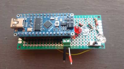
Here's the front of the perfboard. I'm using an Arduino Nano clone. I'm using USB power for both breadboard and the (final version) perfboard, though I put in a screw terminal just for practice, and in case I want to explore actually providing power via the VIN pin. The little stubs of wires, red and black, are just to remind myself which is power and which is ground, not that I would ever make a mistake.
My first surprise is how hard it was to put the LEDs where I wanted them. I have seen them mounted flat, flush onto the surface of the board; however, I saw an Adafruit video which suggested wrapping the resistor wire around the anode wire, twisting and them soldering the resistor directly to the LED. This seems cool, but as you can see my layout is all over the place. I'm not blaming Adafruit; come to think of it, maybe I was supposed to push the LED leads through, and THEN solder the resistor onto the anode. Hmm, that would put the resistors on the bottom side of the board, but I don't think that's such a terrible thing. Live and learn. Maybe she was referring to LEDs used in "wearables" projects.
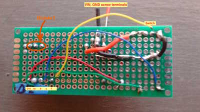
Per a tip from @dronebotworkshop, I planned and wired the ground and power first, with 22 gauge solid wire. This included a 2-screw terminal connected to VIN, though I haven't tested that. I tried to use just one wire, and solder it down along my planned route. I love my super duper wire stripper, but for shorter lengths, it tends to strip the entire wire, and is giving me fits. I'm considering options. Any suggestions welcome. 🙂
After doing some continuity checks, I went on to the data signals, with 30 gauge solid wire. My wire stripper won't handle wire this fine, at all, so I alternate between my fingernails and a small utility knife. A different stripper may help, or possibly just getting 28 gauge wire, though I'd like to get better with the small stuff.
So I used red, green, blue wires for the LEDs of the same colors. Normally I'd try to avoid red for anything except power. Also per Bill's suggestion, I tacked down the corners of the microcontroller (or socket, actually), and then did not solder any other pins except as I was ready to actually use them. And it's true! Soldering onto a pin is much easier than soldering onto an existing solder blob. Not that any of my solder joints are blobs; see photo.
So, wired it up, then tried it. Of course, it didn't work. The red LED stayed on all the time, and none of the others ever lit at all. I used a logic probe; all my 5V and Ground were proper, high and low, respectively. I checked the tops of the pins on the microcontroller, on the front side, and they went high and low in the proper order and proper timing of my sketch, so at least that was something.
It was at this point I realized I'd soldering all my data lines to the wrong side of the Nano. Let's all say, "Oh, that could never happen!" Well, it happened. So I clipped those wires, and moved them to the correct side of the chip. Now it works, hurray!
I had picked D11, D10, D9 for the Red, Green Blue data lines, because they allow PWM, thinking for the future. I put the switch on D8 for the breadboard, but decided to move it to D7, because I'm just not confident enough to solder 4 pins in a row without bridging some of them. Anyway, the switch (shown in yellow wire) doubles everything in the pattern, twice the blinks, two times the On and Off intervals.
That's a wrap. Next stage is to clip the leads best I can, then keep it as a test device (of some kind). Because the Nano is in a socket, I could take it out for other use if needed. Many thanks to @dronebotworkshop and @codecage for hints and suggestions.
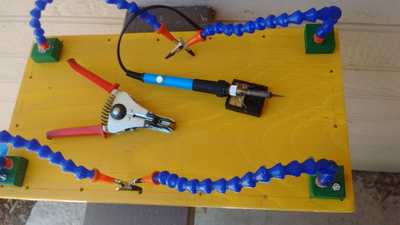
This next part may only be of interest to others struggling with their tools. This picture is of my homemade helping hands, a very modest soldering iron I may upgrade soon, my wire strippers I love but not for short wires and they don't handle fine wires at all. There's also the tiny soldering iron stand, containing the smallest sponge I own. Cheers!
In theory, theory and practice are the same.
In practice, they're different.
Here is what I use for stripping 30ga wire: Wire Wrap Wire Stripper
Although I sure don't remember it being this expensive! Has I been that long since I bought mine?
SteveG
@codecage - A little pricey, yeah. Still, if it works, that's good. As I mentioned, I was thinking of copping out, and just getting 28 AWG wire, or thicker. But maybe I'll stick with it--and learn to wire wrap, too! Thanks for the recommendation. - John
In theory, theory and practice are the same.
In practice, they're different.
@jbo,
When doing wire wrapping you need pins to "wrap" the wire to. Here is a link to a IC socket that has the pins necessary for wire wrapping: 14 Pin Wire Wrap Socket from JameCo
I need to post a pic of a S100 board I wire wrapped years ago so you can get an idea of the work involved on something with more than a few components.
SteveG
Ah, I see. I think I did see mention of that - normal socket and header pins are not long enough. But I just conveniently forgot it 🙂 Thanks, John
In theory, theory and practice are the same.
In practice, they're different.


