I built a 4WD robot using the guidance and inspiration of the Drone Bot Workshop. Its purpose is to provide a Do It Yourself robot kit for my FIRST Robotics students to build at home during the pandemic, using "zoom" classrooms. The robot is controlled by an Arduino Mega 2560, uses the TB6612FNG motor controllers, Opto-isolators for speed control where I use interrupts in the programming, an HC-Sr04 for collision avoidance, and radio control using a pair of nRF24L01 transceivers. In addition, for fun I added a sound circuit, an oscillating sound generator that I call the "whoop-whoop" circuit. To help out the radio transceivers, I added a 3.3 volt regulator using LD1117V33C module on a breadboard. I have been able to run the radios on max power with the separate 3.3 volt regulated supply.
I can post my manuals, schematics, and the programs developed if I figure out how to do that on the forum. I have been able to get everything to work, but not ideally yet, and the students have been building these robot kits at home. But the Drone Bot Workshop has given me the ideas and the confidence to do this. (I will say getting the transceivers to work was and is the most difficult challenge).
I can post my manuals, schematics, and the programs developed if I figure out how to do that on the forum.
That would certainly be of interest to some of us.
On the top right you should see,
How to Add Code to Your Post
How to Add Pictures to Your Post
How to Add Video to Your Post
Post in forum Robotics,
-Other Robot Projects
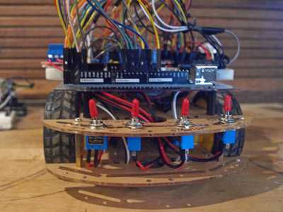
This pic is the rear view of the DIY robot. You can see the ON/OFF switch on the left, the second switch turns the autonomous mode on or off, the third selects the run with the HC-SR04 or on radio control, and the fourth turns on or off the "whoop-whoop" sound generator. The speaker is mounted on top of the 9 volt battery box.
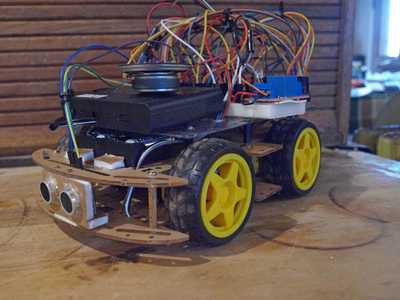
Here are two shots of the DIY Robot. The front view shows a housing built out of foam board. The 6 volt battery box goes in between the second and third level. The 9 volt battery box is mounted on the third level.
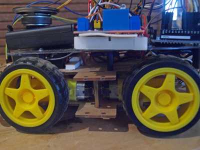
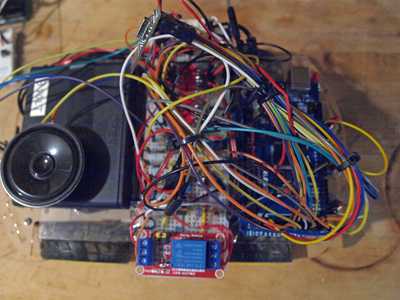
Here is a closeup of the left side. You can see the motors mounted in between the Level(0) and Level(1). I put a small piece of two sided tape underneath the motor to help stabileize the motor, as the kit mount wasn't very good. The top view shows the breadboard and the Arduino Mega 2560 behind the breadboard. Lesson learned: I have two battery boxes in the front, should of had the 9 volt box in the rear, and put the Arduino Mega in the front. With the heavy front, the wheels strafe when turning on carpet, and the robot struggles to turn. I might be able to help that as I found some omni directional wheels (that might help with the side motion).
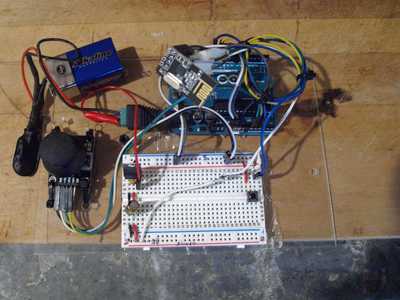
My last pic is the Driver controller. This robot uses the nrf24L01 radio transceivers, and so one needs a separate controller to do that. I built it on a thin sheet of plastic, its basically a joystick, Arduino Uno, and a breadboard. The final version has a ON/OFF switch (not shown in this pic). I added a 9 volt to 3.3 volt regulator go give regulated voltage with greater current than the Arduino power supply can supply. I have been able to get the robot to work with the RadioHead library reliable program, and use higher power, but you MUST have a bigger supply or it won't work at all. These radios are a bit fussy about unsteady voltage, and you must have adequate filtering (capacitors) to take out voltage spikes. (Voltage spikes are a concern with the PWM voltage control. If you look at a square wave on an oscilloscope, there is always a little overshoot at the leading edge of a square wave, and that spike at best is electronic noise to a radio receiver, and at worst can fry electronics with too high an instantaneous voltage).
Here are the schematics for the robot (except for the driver controller).
Here is a separate pic of the Drivers Control Station. I put three pushbuttons for future use, the idea with pushbuttons is for the driver to be able to control some devices, like the whoop-whoop sound, from the drivers controller. That being said, I haven't yet figured out how to add additional channels to the RadioHead radio control, although I did add a third channel.
Thanks for sharing.
What app do I need to view the schematics?
It opens with WordPad but just shows cryptic characters.
Your bot looks very interesting, I hope to peruse your posts one evening when I have more time, and thanks for sharing. 👍
The schematics came right up in my Mac pages word processor that can read .doc files so ms word will be able to read them too. They are hand drawn circuit diagrams so maybe WordPad could not resolve them. Whilst I had the docs up I saved them as pdf files in case this helps you and I have attached them to my post.
Very compact little bot! Wondered how you went with using encoders for odometry with the four motor driven wheels.
My intention was to post in Microsoft Word. I could repost these as jpegs if that will help.
I used the code from the Drone Bot Workshop, which was written for a two wheel robot. Basically, I only used the encoder signals from the two back wheels to determine what the motors are to do. When going forward, for example, the two rear encoders will be the feedback information (the program uses an "or" logic to determine the first wheel that meets the logic). When directing to go forward, the program will control all four motors based on the information from the rear encoders.

