I was lucky to find a bunch of wheelchair motors at my local salvage yard, for USD $.50/#. That is dirt cheap for all of you on the metric system. 🙂 Also, I have been buying a variety of big geared DC motors, 3 phase brushless DC motors and linear actuators.
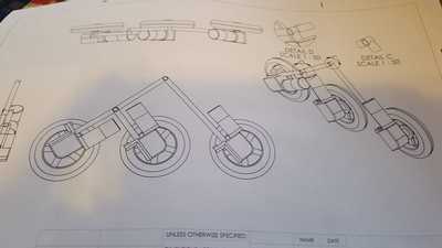
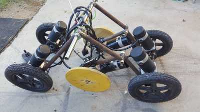
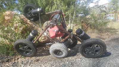
I've always want to build an AWD rideable, outdoor robot. But when all these motors came my way, I decided what is better than 4WD, but 6WD... This lead my research to platforms for 6wd rovers, and over a couple weeks, I came to the conclusion, for outdoor, rough terrain use, the rocker bogie Mars rover platform was really good. So based on the designs of many, many people before me, I designed my own suspension in Solidworks. I used 1" steel tubing for the main suspension components, because the wheelchair motors clamp directly to this pipe diameter. Unfortunately, my motor purchase did not include enough of the top clamp pieces, so I had to cut up the 3 I had, to mount 6 motors. I think it will work out.
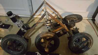
Yesterday I finished the rough fabrication. I had never notched tubing before to make "roll cage" style welds. So that was a new skill for me. I used the drill chuck and a hole saw on my milling machine to notch the pipe.
Today I mounted the motors. I also had to fabricate 2 wooden temporary wheels, because I only have 4 actual wheelchair wheels, currently. The way the rocker bogie suspension works, requires the presence of all 6 wheels. Hence the plywood stand-ins for testing.
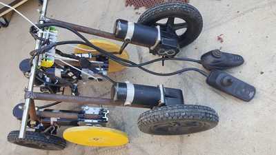
I then made a quick wiring harness and wired up 2 wheel chair ESC/controllers. I left the middle two wheels in neutral. Wheel chair motors have an electric brake, or can be put in neutral by a lever on the gearbox. I hung a 24v aircraft battery from the temporary main pivot point, and did a walk behind test.
Proof of concept success. Holding both controllers, one backwards, and left turns being right turns... I could walk behind the robot and drive it around the gravel yard. Due to the way the motors are mounted for better ground clearance, one pair of motors has to be driven "backwards" in order to go forwards. However, the wheelchair controllers, by software, go slower backwards, than forwards. So just flipping one of the joysticks around in my hand, did not work well. I was able to use the speed controls to limit the pair of motors going forward, to more closely match the speed of the motors going "backwards", but it still resulted in skidding tires. I think the way to do it is reverse the wiring of the motors, so both and later, all three, controllers can be going forward.
But all of this is just initial testing of the drivetrain and suspension. My Flysky (Thanks, again, Bill for the tip!) should be here Tuesday, and then the real fun begins. The biggest question next, will be if I am going to try to implement the original wheelchair control systems, or build a custom ESC(s) * 6, or find off the shelf units, that won't break the bank, but can handle 450 watts * 6 motors.
This whole project needs to be off road, all-weather, capable. I would like to be able to ride it like a scooter/go cart etc. I would like to be able to use it as a power wheelbarrow/lawn cart when not being ridden etc. In other words, a human seat/standing platform needs to be swappable with a cargo hold. I also want it to be a general purpose platform for: AI, machine learning, vision systems, LIDAR, a robotic arm, surveillance, maybe a mobile drone landing pad, and also future autonomy projects. I would also like the project to be scalable up or down in size. I have some really big geared DC motors that could lend them selves to a 6wd rover the size of a golf cart or small car. I would also like to make a mini version of this. Possibilities are endless.
If anyone wants the Solidworks files, please let me know.
Imagine by thought, create, don't wait, Scott.
Wow with something that big and powerful the opportunities would be endless. What about a camera and driving it with goggles (FPV) like a drone?
I'll be watching your project. Have FUN!!!
I just watched a video of a 6wd robot plowing snow. I have a couple linear actuators, and I live at 6000' where we get snow, so a remote (FPV) snow plow could be possible too. It got me thinking of a general purpose front loader configuration like a tractor, ie. snow plow, materials bucket, etc.
Imagine by thought, create, don't wait, Scott.
Wouldn't you need to load it down with a lot of extra weight to get it plowing snow ?
I think you should get an extra motor and rig it up as a snowblower instead. That way you wouldn't need as much weight for traction and could always tell where it is over the snowbanks 🙂
Anything seems possible when you don't know what you're talking about.
@will Not sure I need to add any dead weight. It is already pretty heavy as is. Each wheelchair motor is a bit of a beefcake. In today's testing with only a single 24v battery, the whole unit is pretty heavy. I can lift it and move it around, but not easily. Eventually, something more advanced than lead acid batteries would be a goal, at which point some added weight might be needed. Of course it all depends on how much snow, density of snow etc...
Imagine by thought, create, don't wait, Scott.
Maybe just more ( 2x24V or 4x12V) batteries for extra power, they'll drop off in freezing weather.
Anything seems possible when you don't know what you're talking about.
Six motors certainly complicates things. If you have the electronics know how you could probably tweak the controller circuits already there.
How does it go with a 360 spin around? I notice the Mars Rover vehicles have steerable wheels.
How does it go with a 360 spin around? I notice the Mars Rover vehicles have steerable wheels.
Yes. I opted to not incorporate steering wheels in the traditional "four corner" wheels on the initial Rover build. My thought was get something working, sooner than later, and add features, as time/budget allows. Steering wheels would likely be one of the first major drive train upgrades. Of course, that means driving 10 motors, instead of a measly 6, just for locomotion. And the navigation code, well, still wrapping my head around the geometry.
I am still testing the very basic motor mounts, and suspension components, with only the 4 "corner" wheels powered, and the middle wheels in neutral. It is very, very kludgy, holding the two wheelchair controllers, one backwards, for testing - tethered by a generous 60cm or so... 🙂 ***EDIT: I will probably reverse polarity of half the motors, so the controllers will be more intuitive, and not have to be held opposite each other. The reason I have not done so already, is the motors and controllers, have really nice, hi amp, Anderson connectors, and I didn't want to cut and splice hastily. *** It will spin 360* like a tank, if I can coordinate my hands to hold the controllers without dropping them, and simultaneously, not climb a robot over my boots, shins and kneecaps at the same time. It appears wheelchair controllers have a built-in speed parameter from forward to backward movement. Therfore since half the motors are running "backward" I have to adjust the speed parameter on the wheelchair controller. This robot has some serious weight, and traction is very good, but that means any difference of rotation speed of wheels, and things go bonker, right quick. Either dragging wheels, controllers current over-limit errors etc. So hand controlling, as a means of testing is running out of usefulness, quickly.
Anxiously awaiting the Flysky. I am starting to come to the conclusion, I will be building or buying ESC/PWM motor controllers for this. This entire robot is built from scrapped/repurposed/recycled bits and bobs, so spending $500 for speed controllers is out of the question. However, I am thinking these wheelchair controllers, may be better served sold on eBay and proceeds shifted to something more suited for the task at hand.
Currently looking into: SSR DD 60 amp units, in an H bridge, controlled by PWM from microcontroller, fed signals from Flysky.
Imagine by thought, create, don't wait, Scott.
It is not all that clear to me how the controller and motors are wired together from the pictures. Are the two back wheels connected to one controller and the two front wheels connected to the other controller? In theory you only need one motor on each side which chain drives the other two wheels on the same side. In other words you drive it like a tank. The motors on each side would be going the same way, forward or reverse.
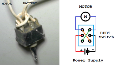
When I was testing the motors on my robot base I used self centering toggle switches. They were easy to hold in each hand and move the switch forward or backward. I could follow behind controlling it like a tank. Of course there is no speed control but apart from the jerky start and stop it worked fine. Later I added the two h-bridges.
To enlarge image right click image with right mouse button and choose Open Link in new Window.
If you stick to using just four motorized wheels I think you will have a very useful outdoor robot base.
@robotbuilder Thanks for the tips. Some of my first robotics projects were using momentary DPDT switches like that, connected to headlight motors in a robot arm. I agree, it would be good for simple testing. In answer to your question, the middle wheels were in neutral, and the front wheels were on one controller, and the rear wheels were on the other. That all changed today.
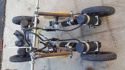
Rewired the motors, so that the 4 "back" motors are on one controller, and the 2 "front" motors are on the second controller. None in neutral, all contributing to drive power and traction. I corrected polarities, so now I can hold both controllers in the same orientation, so it is not such a minder-bender operating it.
(Side note, some wheel chair motors will run one direction and others the opposite direction when red/black wires are the same - notwithstanding a left motor vs a right motor - the wire colors are opposite. Now I know.)
I also added 4x 1" bore pillow block bearings and 1" main suspension shaft. (all salvage yard stuff, of course). I also was given 2 temporary middle wheels, that are better than my plywood surrogates.
I have seen the 4x4 Box style bots like in the video above. They are VERY capable. But I wanted better. I want full articulated suspension and 6wd and stair/obstacle climbing ability. I have seen many 6x6 rocker-bogie rover style bots, but NONE are of the size I am doing. Maybe this is a first? I have scoured youtube and various blogs, and not found anyone doing a big rover like this one.
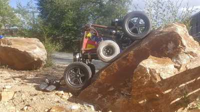
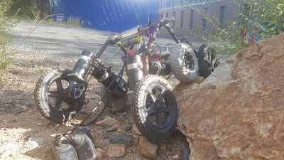
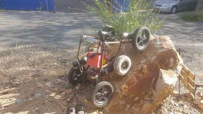
I'll add some pics to show today's proof of concept. Notes:
Camera was held level to horizon in all pics. Asphalt seen in background is sloped. (Not playing camera/angle/scale tricks here. The boulders are probably several thousand pound beasties) Robot conveyed itself to all positions with no physical help, just operating the joysticks. About 45* rock face is about max before wheels spun. Note articulation when only one side had rock interference. The obstructed side could easily climb about 3x higher than the side on the ground with no problem. At all times ALL 6 wheels were contacting something - never in mid-air. I look forward to a stair climb test, but I think it will have no trouble.
Finally, I have been thinking more about the universal platform that this rover will hold in the future. It will be based on linear actuators, resemble a front-loader bucket as seen on tractors and back-hoes etc. It will be modular to hold attachments like: materials bucket, forks (lightweight palletized cargo, small firewood logs, metal stock etc), snow plow, robot arm, AI navigation sensors & cameras...? My thought is that the payload can swap out for whatever I am working on. And this will be the platform to get the modular payload somewhere interesting.
Imagine by thought, create, don't wait, Scott.
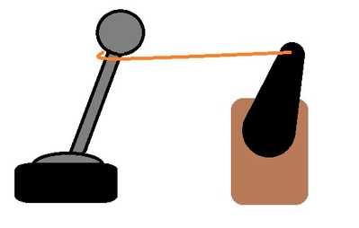
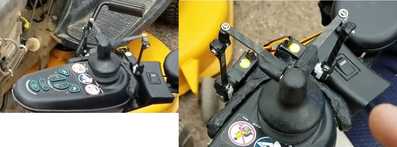
Although probably an ugly hack I thought maybe two servo motors could be used by an Arduino or RPi to mechanically control the toggle handle on the controllers. One would pull it left or right and the other forward or backward. They would be positioned at right angles to each other. These could even be the servos used in remote controlled cars so you would have radio control.
Very cool. I thought about doing something like this to make use of the wheelchair's motor controllers. Servos controlled by radio control and receiver with a mechanical linkage seems pretty straightforward. I still might do this as an interim solution.
However, I think the endgame is direct control of the motors, adding encoders to 4 or maybe all 6 of the motors, and maybe using 2 of the integrated brakes in the motors, and disabling the other 4 brakes. The wheelchair motors, handle the brake release automatically, but there is a continuous 24v draw on the brakes, when not in motion, to hold motor armatures solid. Not terribly efficient.
A PWM output from microcontroller to an ssr such as an SSR DD 60amp, per motor should be pretty basic. It gets a bit more complicated setting up an H-bridge for reverse, which is necessary. I would be looking at EDIT: quantity twenty four (24) SSR-DD-60, to do a full H-bridge with 2 dedicated SSRs per motor. The other option is off-the-shelf motor controllers, but they are not cheap, and as you can see, this entire robot is built on a scrapyard budget. The motors are 24v and rated 450w, peak of 500W. So that puts their draw at about 21 amps. But since there are six, it is quite possible that none will ever see that kind of current. But it definitely dictates a motor controller of somewhat respectable size.
On that note, it also occurs to me, I could add temp monitoring on each motor, and possible run them at even higher voltage, say 36v max. On flat ground with all 6 motors contributing, the current and heat might stay within range indefinitely. But not sure I need a racing rover.... Fun to consider, though. Maybe just have a "turbo" mode, for short bursts.
Just for fun yesterday, I put the speed controllers in the fastest mode, and pushed full forward on both joysticks. I could keep up, but it was a brisk walk behind it.
Imagine by thought, create, don't wait, Scott.
BTW, if anyone knows of an off-the-shelf, low cost, generic, speed controller that might fit the bill, please let me know. Most of the stuff on eBay is designed with a turn-pot input, not pwm microcontroller input. superdroidrobots sells all kinds of stuff that would work, but price is WAY beyond my budget. Or if anyone has a few speed controllers in their unused parts draw they want to barter, please let me know. I have lots of cool trade/barter items.
Imagine by thought, create, don't wait, Scott.

