This is a continuing story of a project I have been engaged in for some time. It started with a request from the robotics team for a prototype board that would allow them to operate their own/brush motors without the robot brain attached. It has morphed into me learning how to actually build something robust enough to survive contact with the outside.
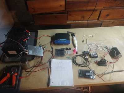
In this picture I have some of the components laid out for powering the CIM motor on the right. I also have a list of things I need to go get, inorder to proceed.
One component I am missing is a PDP (power distribution panel) or a fuse block. I also have to fab up some sort of wood base to support the components. I have a bunch of fiddly connecters to attach as well.
What hasn't been pictured is the charging source for the batteries. That's just some pedestrian solar panels.
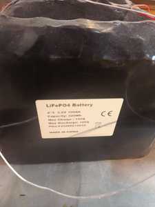
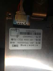
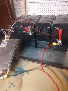
I am powering the project with a LiFePO4 100ah battery pack from battery hookup. It was $240ish hence no fancy cover. I realize I have to get up to speed on the foibles of these new batteries.
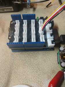
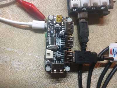
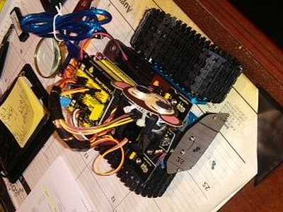
I suppose the heart of the project is the Raspberry Pi Zero W2 hidden under the Zero4U powered USB hub. I really struggled with this part. I wanted a permanent connection between the Arduino and the Pi but could not figure out to program the Arduino over something other than USB if the Arduino loses it's programming or memory. So I punted, and just keep it plugged into the pi via the hub hat. Pi Zeros only have one USB port for data, so you need a hub if you have more then one USB device to plug in.
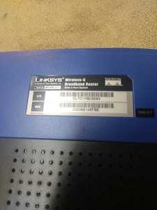
If you notice a lot of WiFi stuff, it's because the ultimate goal is to have this set of components operating remotely. That is why you see the Linksys WRT54G router. Back in the day, this router came with removable antennas. It is also is reflashable. I currently have DD-WRT flashed, but could have Open WRT or AREDN. With it's LMR 400 cable and parabolic 2.4 GHz dish attached, this router can send data a solid 1/2 mile, and up to 3 miles. It can stay up for years too.
@DuelFuel, Nice setup!.. I have just completed testing on my KeyeStudio tank Robot.. It has a number of sensors that came with the kit and are now attached and tested.. IR control, HC-SO4 ultrasonic, photo sensors, a servo to turn the HC-SO4,and Bluetooth to run it off of my iPhone..
I have purchased a Huskylens AI camera, and am now working to mount it on the robot tank to make it line follow and object recognition..this part will be real fun trying to code all of that stuff...lol
LouisR
I looked at the specs for the kit. I am familar the the L298P motor controller. It's a very well documented H-bridge. I have a few of those around here. The blue tooth radio module was the first add-on part I used on my first raspberry pi model A. I used it like a WiFi radio. It was horrible. Wow! I was really ignorant in those days, but it was sure fun to learn. I like how your kit is powered by 18650 Li-ion cells. I am very busy migrating towards them. I believe they will be the new "free" batteries like car batteries used to be.
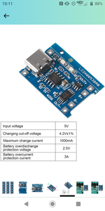
I am assembling these charging chips and cheap lil plastic battery holders for gang charging a bunch of individual cells. I am also assembling the spot welder for building the larger S&P packs.
Looks like your kit uses Arduino IDE, so should be also well documented. That and a fast internet connection makes life livable when embarking on these projects!
DF
@DualFuel, Indeed.. I have several Arduino UNO Atmega328P boards, and planning to get a few ESP32's an a ATmega2650 for a project I am considering doing.. a remote surveillance camera with object tracking to shine a lite on the intruder...lol
I;m working my way up to WIFI, as I thing that will be a better choice for distance and simplicity..
Be safe, and have fun !
LouisR
LouisR
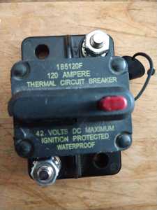
This is a main switch for the project. This is a surplus switch from the robotics team. I have seen the same or similar switch in one of Will Prowse's setups in one of his LiFePO4 battery videos. I assume they are readily available... although these days that may not be the case.
If I hadn't found this switch, I would have used a knife switch from the old knob and tube wiring pile. If I hadn't had that I would have used a AC house switch. These choices aren't as ideal as a sealed switch that won't spark.
Is it possible to jump across the terminals with a resister to feed the caps slowly then throw the main switch? No spark?
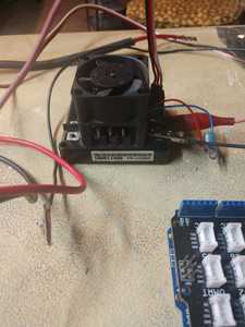
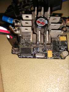
I struggled with the Victor 884 not powering the motor. I had pwm output to the serial monitor, some voltage readings at the pwm
Cable ends, and I had power to the motor controller. On a hunch, I stripped the plastic cover off the controller and jammed the pwm wire in tightly, and Viola! The motor took off.
If I use the Victors, I better solder something more permanent on the controller.
Indeed, A good connection is paramount to making everything work right..In the business, we called a bad connection a "high resistance short"..very common in termination cabinets when sometimes the electricians get in a hurry and end up with part of the wire insulation in the connection block. hard to find when you have a complex wiring of a industrial motor controller ! lol
The other thing I might mention is that I usually "tin" (soldering the bare wires) before I would terminate them, even if I were using a crimp on connector of some type..This is particularly important on small gauge wires( under 16AWG). Glad you found the problem, and are now good to go!...
kind regards,
LouisR
LouisR
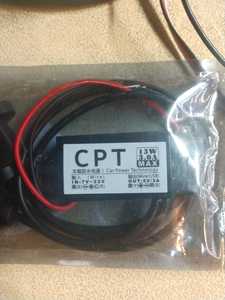
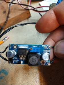
I cooked a voltage regulator in an Arduino Uno, for what ever reason, so I installed a buck converter to bring the LiFePO4 battery voltage down from 13.1vdc to 11.7vdc. I am not sure if the excessive voltage cooked it or having the power and USB plugged in at the same time. I thought the Uno could discriminate between sources and choose one over the other. Regardless, I thought it was wise to add the buck converter to bring the voltage into the recommended level.
@DualFuel, Although the Arduino specs says that 20V is maximum voltage input to the boards jack, the input capacitor across the 5v regulator is rated @ 25 V, at least on my UNO board, so that would be the maximum voltage you should input to the board.. http://arduino.cc/en/uploads/Main/Arduino_Uno_Rev3-schematic.pd f" target="_blank" rel="noopener"> http://arduino.cc/en/uploads/Main/Arduino_Uno_Rev3-schematic.pdf
The 5 v regulator chip is only supplied by the power jack. The USB will power the 5 v and the 3.3 v bus, and is isolated from them by a comparator circuit that compares Vin to the USB input bus voltage. This is why your UNO continues to function with the USB.
Check your UNO board and it should tell you on the top of the cps what value (ie 47uF 25V) or what ever your says..
Maybe the poly fuse on the the Vin side is blown as it's only rated at 500 mA.. check that first..
Regards,
LouisR
LouisR
Hi @Dualfuel,
I have tried to explain how I think your system is behaving, but sadly this is a 'long story'. You might want to skip to my 'Way forward' recommendations at the bottom on first read, but I hope the 'full story' will be helpful for the future.
---------
You say you cooked a voltage regulator ... but not which one! Looking at the schematic referenced above by @inst_tech shows:
- U1 ... shown as ncp1117st50t36 ... but probably ncp1117st50t3g
- U2 ... LP2985-33
U1 reduces the incoming power jack voltage down to 5V
U2 reduces 5V to 3.3V
I assume, U1 is the device that was 'cooked' .. that being the case, then:
- As &inst_tech notes, the 5V supply is switched .. if the power jack voltage is over about 6.6V, then the power jack voltage is sent to U1, and 5V line is powered by U1, otherwise 5V line is driven by the 5V supply from the USB socket.
- So to power via the jack socket the voltage should be confortably over 6.6V ... maybe 7V upwards (The estimate of 7V is taken from the schematic ... not confirmed.)
- But what is the maximum input voltage ... this is a little more complex, as there are several factors to consider
- The 1117 data sheet has an 'absolute maximum' of 20V for all voltage versions of 1117, and a specified range of Vin = 6.5 V to 12 V for the 5V version, suggesting that a max of 12V is probably wise, although it should survive up to 20V.
-
- Input capacitor PC1: I don't have a UNO to check, and the schematic doesn't show a voltage rating, but providing it is at least 20V (e.g. 25V as suggested by @inst_tech), then it is not a limiting factor. I will ignore if for this discussion, assuming it is at least 20V.
- Power dissipation: This is likely to be more important limit.. but unfortunately the most difficult to estimate. (NB purists will note the following ignores some small factors)
-
- U1 is linear regulator, so that the power dissipation is given by:
- Power dissipation (mW) = current flow (mA) * Voltage Drop
- where Voltage drop = Input Voltage - Output Voltage
- Say Input Voltage = 13V, Output voltage = 5V, then Voltage drop = 13-5 = 8V
- Current flow ... Take 200mA as an example ... you need to measure this, noting it will change with program flow, etc. Measure current flow to power jack over as many different conditions as possible
- So Voltage drop = 8V, current = 200mA, then Power dissipation=8*200 = 1600mW
- Now another tricky point ... would 1600mW be too high?
- U1 is linear regulator, so that the power dissipation is given by:
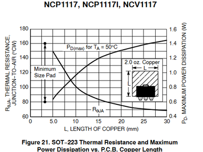
The onsemi datasheet ( https://www.mouser.co.uk/datasheet/2/308/NCP1117_D-2307187.pdf) for the part includes:
This shows that the power dissipation depends upon the PCB track arrangement, making a 'firm' determination impossible - the range being roughly 600mW to 1400mW. Unless you can measure the PCB track size, I would recommend, aim for the 600mW!!!
Hence, if your card was taking about 200mA, it is now obvious why the voltage regulator was 'cooked' .. literally!
-------------------------
Way forward suggestions:
- measure the supply current and voltage drop ... recalculate using the above calculation method
- Using your buck regulator as a pre regulator is a good idea ... but reduce the pre-regulator output voltage to a convenient minimum, thereby reducing the 1117 power dissipation. As a starting point I would try 7V, but you may need a slightly higher value.
Good luck! Dave
Thank you for the comprehensive analysis of the Uno's voltage regulators. Your work is useful and appreciated, I have to test the Uno with the USB cable to see if it still works. Also, I would be remiss if I failed to add that the Uno is not genuine Arduino, but a Chinese clone. I don't know if the components are identical, and of the same quality. I know the main processor is square not rectangular. I was in rush to answer and don't have the board near me right now.
Thank you for your thoughts on the Uno. I will let you know what turns out to be wrong with it ...I might have to fix it, they aren't $3 anymore, LOL!

