Bill said in one of his YouTube videos, that I2C is not practical for longer connections. I want to share with you my experience, which proves his point. I had intended to control 512 micro servos over 32 PCA9685 servo controllers, all stringed together with an I2C bus with a total length of about 1 to 2 meters.
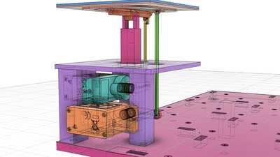
The servos are split into "modules" of 32 each, each module having 2 controllers.
So I built the first servo module, containing 32 servos and two PCA9685 boards and connected it to a breadboard and the breadboard to a Raspberry Pi which runs the Python code to control the servos.
It worked fine with an I2C bus of 10 cm length. However, when I grew the bus to 30 cm length, it already stopped working. I made two videos to show the result:
10 cm bus:
30 cm bus:
As you can see, at 30 cms, the signals are basically random.
I added two 1k pull up termination resistors to the bus lines as recommended, but that made no noticeable difference. I am also not sure, if the PCA9685 boards don't already contain the pull up resistors.
It looks like I will have to find another way, to control the 512 servos.
The option that I am currently considering is to have an ESP32 control 32 or possibly 64 servos close by (via the PCA9685 and I2C bus as in the test) and then send the steering commandos from the Raspberry Pi to those 16 or 32 ESP32's by WiFi. The software will generate up to about 10000 servo commands per second, and most simple bus systems (UART e.g. seem to be too slow for that.)
Feedback and suggestions welcome.
Those are great videos, thanks for sharing them!
It looks like I will have to find another way, to control the 512 servos.
I just have to ask - what are you building that requires 512 servo motors?
😎
Bill
"Never trust a computer you can’t throw out a window." — Steve Wozniak
They say if you break a mirror you get "7 years of bad luck". So be very careful that you don't drop your whole project, or the next 1792 years will be pretty miserable for you!
😲
That is one amazing project, please be sure to keep us updated with more video.
And on the I2C side, have you considered using an I2C multiplexer to divide your output into several independent I2C busses? Might be a way around the situation with long wires.
😎
Bill
"Never trust a computer you can’t throw out a window." — Steve Wozniak
And on the I2C side, have you considered using an I2C multiplexer to divide your output into several independent I2C busses? Might be a way around the situation with long wires.
I could try that, even though I don't have address conflict issues, just to improve the bus signal.
Have you or anybody else by chance any experience with I2C extenders like this one: Adafruit LTC4311 I2C Extender ?
@dronebot-workshop
I have now tested the Adafruit LTC4311 I2C Extender and it worked like a charm.
https://www.adafruit.com/product/4756
Whereas before I ran into trouble with just 30 cm of bus cable, after I inserted this board after 10 cm I could add another 80 cm of bus cable without any problems. I have not yet tested the maximum length.
OK, I have an update and a confession to make.
It turned out, that the LTC4311 signal enhancer was not really necessary and the I2C bus would work quite well, if I had not made an embarrassing rookie mistake:
Apparently the ground cable that I used to power the pwm-controller-modules was too thin (it was just a jumper cable in my test build). So whenever I made large servo movements with many servos at the same time, the cable was too thin for the power and it messed with the ground of the bus (which is the same ground) and that messed up the signals. Duh!
Once I made the power cables both massively larger, all the problems went away.
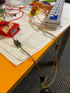
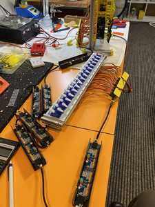
In today's test I daisy-chained 16 pwm-servos-modules together (see picture below). The total bus-length, including the 16 servo-modules, was about 3 meters. I attached a total of 64 servos, 32 on the first 2 modules and another 32 servos on the last 2 modules. I tried it both with the LTC4311 in the chain and without.
The bus was attached to a Raspberry Pi 4 and I had cranked up the I2C bus speed to max. The test program was written in python.
Differences:
1) Without the LTC4311 the max. throughput was about 5000 commands per sec., but I saw fluctuations in bus speed and every now and then a command would fail if running at max. speed. With the LTC4311 it was about 3200 commands per sec. at most, but no fluctuations in bus speed and no visible failing commands.
2) At a more "normal" rate of just a few 100 commands per second the bus worked fine with or without the LTC4311 over the full 3 meters and all 64 servos.
As a side note: I had also run the bus on an ESP32 at max speed (in C++) and I could crank out 10'200 servo commands per second with no problems on the bus and no lost commands. (I had to tune the Adafruit library a bit for that.)
Lessons learned:
1) Make sure you use thick enough cables on your pwm-control-modules or you mess up the I2C bus signals.
2) The I2C bus is faster than expected and can be longer than expected if you override the default speed and if you avoid power surges.
I have not tested the longest possible I2C bus before it fails and if the LTC4311 would extend that length.
And if anyone is interested in the 4 x 4 prototype:
Bill said in one of his YouTube videos, that I2C is not practical for longer connections. I want to share with you my experience, which proves his point. I had intended to control 512 micro servos over 32 PCA9685 servo controllers, all stringed together with an I2C bus with a total length of about 1 to 2 meters.
The servos are split into "modules" of 32 each, each module having 2 controllers.
So I built the first servo module, containing 32 servos and two PCA9685 boards and connected it to a breadboard and the breadboard to a Raspberry Pi which runs the Python code to control the servos.
It worked fine with an I2C bus of 10 cm length. However, when I grew the bus to 30 cm length, it already stopped working. I made two videos to show the result:As you can see, at 30 cms, the signals are basically random.
I added two 1k pull up termination resistors to the bus lines as recommended, but that made no noticeable difference. I am also not sure, if the PCA9685 boards don't already contain the pull up resistors.
It looks like I will have to find another way, to control the 512 servos.The option that I am currently considering is to have an ESP32 control 32 or possibly 64 servos close by (via the PCA9685 and I2C bus as in the test) and then send the steering commandos from the Raspberry Pi to those 16 or 32 ESP32's by WiFi. The software will generate up to about 10000 servo commands per second, and most simple bus systems (UART e.g. seem to be too slow for that.)
Feedback and suggestions welcome.
I only read this first posting, so if you later found your problem, I missed it.
I did not experience your problem with my project. In the end, I had two BME280's just over 2 meters from the single ESP8266. I never had one problem with them.
BUT... I did have troubles with my servos and it turned out to be the servo libraries were not well tuned to being run on an ESP8266. I finally broke down and wrote my own servo controllers and the random jerking around disappeared. But... I only had two. 😔
https://inqonthat.com/inqvent/
I really never intended this to ever see the light of day again, but I believe I need to prove that 2 meters shouldn't be the issue.
I watch Bill's videos and then just cringe listening to myself... 'Bueller... Bueller... anyone... anyone...'
3 lines of code = InqPortal = Complete IoT, App, Web Server w/ GUI Admin Client, WiFi Manager, Drag & Drop File Manager, OTA, Performance Metrics, Web Socket Comms, Easy App API, All running on ESP8266...
Even usable on ESP-01S - Quickest Start Guide
@inq
See my follow up post here: https://forum.dronebotworkshop.com/postid/17874/
In short: Yes, the problem went away once I made the ground cables thicker and in the end the I2C ran fine on 3 meters of cables.
@mattack65 I shouldn't have to mention this but, the ground lead current carrying capacity has to be the sum of all the concurrent positive leads.
First computer 1959. Retired from my own computer company 2004.
Hardware - Expert in 1401, and 360, fairly knowledge in PC plus numerous MPU's and MCU's
Major Languages - Machine language, 360 Macro Assembler, Intel Assembler, PL/I and PL1, Pascal, Basic, C plus numerous job control and scripting languages.
Sure you can learn to be a programmer, it will take the same amount of time for me to learn to be a Doctor.
@mattack65 I shouldn't have to mention this but, the ground lead current carrying capacity has to be the sum of all the concurrent positive leads.
Oh wow thanks, this shows my lack of electronics and hardware understanding!
Do you have any good beginner links that elaborate on this?
Cheers


