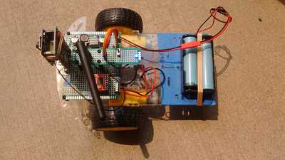
I have completed the robocar! This was the car based on the commonly available 2 wheel robot car chassis, and the excellent article Build an ESP32CAM Robot Car. Here's my project, complete at least to this point of wiring, debugging and initial driving trials. Bill was right, this was quite a lot of fun.
I assembled a chassis several years ago, plus a chassis-plus-breadboard version (based on Build a Robot Car with Speed Sensors) last Fall, and some parts of the circuits worked. I've measured rotations per minute using the rotary encoders plus opto-interrupter. However, I'd never had a fully driveable car before. And the earlier ones were on breadboards; with perfboard, this was by far the most complicated hardware project I've attempted, with so many first time challenges, but still very entertaining. As far as my soldering goes, eh, see someone else's work for an example of how it's done.
All that is by way of explanation, for why I picked the path of trying to duplicate Bill's steps and components as closely as possible. I had enough variables to deal with, so I appreciated having the article, video and proof of a working vehicle to work from. Thanks @dronebot-workshop!
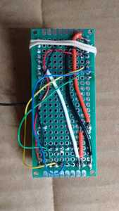
So, I also used the approach of main board, midboard (ESP32-CAM, vertical) and topboard (switch, LED, and antenna). In the photo of the back of my midboard, note I did stick with it, using the 30 gauge wire, solid, for the data signals, though I still find it hard to work with. And 22 AWG solid wire for power and ground connections. Also note the large red wire providing 5V has a kind of "dog leg" instead of just one continuous, straight wire. I appreciate the flexibility of having power come either from the bottom pins attached to the main board (production mode), or from an FTDI programmer attached via the six pin socket. Change the power option just by moving the little jumper on the front. I use this jumper to make my connection for "normal" power. In the end, I was not able to wrap my head around the wiring needed to actually implement the FTDI interface here, so I have the 6 pin socket but am not using it. With the way the ESP32-CAM modules are being sold nowadays, I found another way to get what I needed; see below. Oh, and the rubber band here is just to keep the tiny camera lens in place; otherwise it tends to flop around, pointing too much at the ground, and making for a jarring experience of driving. Who knew?
I had no idea the little 3mm LED would be so bright. Of course, the blue ones are listed as taking the most forward voltage, using the equations and checking with this calculator. I just didn't want it to burn out, so 100 ohms seemed good. Maybe I'll try 470 ohms for the next blue, and use green for the next bot.
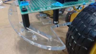
Things to improve? As much as I've worked on this and two previous, nearly identical chassis, I still can't plan all my drilled holes as well as I might. I did learn my less with drilling after everything is attached: don't do it. I cracked one platform, but my duct tape is always there for me. I kind of lucked out with this project, in that in the front of the acrylic base, there is a long channel, not just a round hole, that allows some freedom for placing standoffs. Because the channel is diagonal, it has a lot of "forgiveness" for matching the holes in my perfboard. (7x9 cm seems a standard size).
Next, antennas. I either lucked out and correctly performed the procedure to switch from internal to external antenna, or I lucked out and didn't actually remove the original connection with the zero ohm resistor in the first place. It is so small I can't actually tell. I will have to download that sketch to display the strength of WiFi signal in decibels, and see if my other ESP32-CAM module (unmodified) performs the same. At any rate, I'm pretty sure "gluing" my little wire to the metal cover over the WiFi module is not the best form. Still, I don't think anything was hurt; good thing that metal cover is there.
Also to improve: soldering everything just once. Bill gave some steps that have helped a lot.
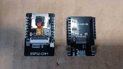
Anent programming the micro-controller module, this photo is a regular ESP32-CAM module next to the special purpose board for programming. This makes all the right connections, provides the right level of power, and has the handy micro-USB connector. So it replaces the FTDI programmer. I know prices come down over time anyway, but the previous $9-10 is now about $5-6, including the programmer board. It even has two little micro-buttons (see photo) connected to Reset and to GPIO 0, very convenient.
In theory, theory and practice are the same.
In practice, they're different.
Congratulations, well done !
Anything seems possible when you don't know what you're talking about.


