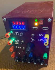
I recently completed a bench ATX power supply project.
Obviously, given where we are, a major influence was Bill's video. As soon as I saw it I knew that I wanted to make a supply with one of those ammeter/voltmeters, but I had my own ideas on how to implement that. (more on this below) I don't know if I got the idea from Bill's video or from another source, but I also stuck with the idea of fusing the output lines.
I regularly have scenarios where I want a -12V rail. A simple circuit can be constructed for this, but for rough breadboarding it's just easier to have a -12V plug, and while I'm at it I might as well expose the -5V rail too.
I own a 3d printer, and had most of a spool of PETG that was getting a little old, so I decided to use this for the case.
Outputs
In addition to the -12V and -5V lines (and the standard +3.3/5/12), I wanted some USB ports. I fiddle around quite a bit with USB-powered devices and it would be handy to have some USB plugs directly connected to my +5V lines.
I wanted each of my output binding posts to have an independent switch and indicator light. I do a lot of work with a 3.3V or 5V microcontroller controlling a 12V (or something else) powered load... and for a lot of the work it would be nice to have a control switch for each independently. If you're going to have something with an on/off switch, it's also nice to have an indicator light for it... so I used some 3mm LEDs showing when each switch is active.
Anyone else copying this type of design should seriously consider the addition of a simple, fully adjustable power supply. I have a fairly bad one that cobbled together that connects directly to wall power that sits comfortably on top of this device and is available for use, and I have a design for a much higher quality one that I will get around to constructing eventually, but I didn't want to hold off on this project until that design is finalized.
In particular, if you want to do current limiting from this supply it needs to be done externally.
One of my biggest breaks from Bill's video was the integrated voltmeter/ammeter.
The design of these devices is a little bit strange. The ground side of the voltmeter is short-circuited to the groundside of the ammeter. This effectively means that we must measure amps on the "low side" of our circuit under measurement.
This is the wiring list from the one I used. Keep in mind that yours may differ, particularly in the wire colors.
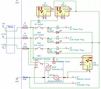
- Thick Red Wire - Current Source (positive side) of the ammeter. Measured current actually flows through an ammeter, so this thicker wire is to handle larger currents. This is connected to our binding post as an "alternative/metered ground connection"
- Thick Black Wire - Output Current from ammeter - Connected to ATX ground. Tied to the "non-metered" ground ports.
- Thin Red Wire - Power for the Voltmeter/Ammeter module - Connected to a PSU 5V line
- Thin Black Wire - Ground for Voltmeter, internally this is dead shorted to the Thick Black Wire. This can be removed.
- Thin Yellow Wire - This is the "sense" wire for the voltmeter. Very little current goes through here, and we are going to connect this to our selector switch.
Because there is so little current going through the voltmeter, you can use a relatively simple selector switch to select which of the binding posts are connected to this lead. I used a 4-position switch that selected 3.3V/5V/12V and "other". "other" is just an open connection that can be used as a voltmeter to probe around various parts of the circuit. The selector actually connects just after the fuse, before the switch... so we can see the voltage drop on the supply from adding our load when we flick on the switch for that port.
To be clear, the ammeter part of the Voltmeter/Ammeter display will show whatever happens to be flowing through a particular ground port on the front panel. The Voltmeter part will display whichever voltage is being selected, relative to that ground. The two do not necessarily need to have anything to do with each other, other than that common ground.
An important detail: This ammeter/voltmeter is designed to work in only one way. You must be very careful about not connecting negative voltage through the "current measuring ground". I realize this is potentially tricky, given that I have also exposed the negative voltage rails, but for the kinds of things I use it for, this shouldn't be too much of a problem.
I also wanted the ability to use a USB port as a "measured" device. I chose the laziest way of doing this, by simply connecting the positive of one USB port to the +5V line, and the negative of that port to the metered ground. This means you won't get an accurate amps reading if you have something plugged into that USB port, AND into the metered ground plug. As the two circuits are effectively parallel, coming together at that metered ground plug, you will of course still get an accurate voltmeter reading.
I have a 3d printer and wanted to use it to make a reasonably nice box for this project. Using up a roll of PETG that was getting a little old would be a side benefit here.
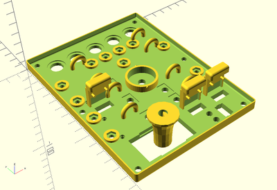
OpenSCAD is my favorite tool for functional projects like this one. It took a bit of work, and the resulting project takes literally about a minute to render, but I'm quite happy with how everything came out. Panel offsets, screw mounts, holes and support brackets for all of the panel-mount components, and even vents in the side of the case were not too difficult to design and implement. Almost all parts were designed parametrically so that I can adjust things like the wall thickness on the fly, and the rest of the model adjusts for it.
The bulk of the print was two different pieces, a "box" which is mostly just an ATX mount, small feet, a few vent holes, and screw mounts for the panel, and a "panel" which has most of the complex stuff.
There's a 3d printing trick to embed text in the plastic of a panel. You print the text in the correct color, then print the rest of the panel in a different color AROUND that text. There are a few special slicer settings and a bit of gcode editing to make it work. It didn't work perfectly, but I did get extremely easy to read text even at a distance.
Unfortunately there was a small mishap with a chair falling against the printer table mid-print on the box itself, so there is a visible seam in the final product.
There was also some issues with what I believe to have been moisture in the PETG roll, leading to a slightly ugly "rough" look on some surfaces. On the other hand, this roughened up the surface enough to more easily support setting my variable power supply on top of this one... so although it didn't work out visually, it did work out functionally.
I have a full wiring schematic in a kicad project on my project page. But in general there are basically 4 almost distinct sub-circuits once you get beyond the input fuses for 3 of them. Aside from a common ground for the indicator LEDs using a bit of perfboard hotglued more or less to the middle of the panel, most of the circuit is fairly straightforwardly wired.
I used wago-style connectors to somewhat independently connect the different parts of these circuits, but in retrospect I wish I had used a female ATX connector to connect it all at once. If you're like me, and don't smartly use a female ATX plug (such as one stolen from an ATX power cable extender), be careful with your sense lines.
I'm not really sure what else to put here, ask questions if you're curious.
It wouldn't be a project of mine if I didn't immediately have regrets.
- My original design had a seperate "earth ground" post, different from the ATX grounds. I did not realize, at the time, that my ATX power supply connected its ground to earth ground. So this was pointless. I could have sworn I had checked this too... 🙁
- Although the 5V post is switched, the metered USB port is not. This is a little bit confusing. I think this would have been easier to see without the "earth ground" post, as I could have located the metered USB port in the open spot where that earth ground post was. Perhaps another option would have been to locate the 5V + metered USB at an extreme end of the selector switch. I'm not sure of the exact solution here, but this interface could cause confusion.
- For the LEDs in particular, you end up with a large number of low current grounds. I connected these on a piece of perf board and it would have been nice to have piece of plastic to mount the board to, rather than simply hot-gluing it in place.
- One possible design "flaw" is that in this design is that the grounds and power are a significant distance from each other. I do not use the ground + power dual-banana plugs, so this is not an issue for me.
- I should have been more careful when selecting the current-limiting resistors for the LEDs. The "power on" and "standby" LEDs are the wrong brightness level (power on should be brighter, but it's dimmer).
- In retrospect I wish the box had slightly thicker walls. 2mm is kindof thin. There were also some avoidable printing issues with the box.
"A resistor makes a lightbulb and a capacitor makes an explosion when connected wrong"
"There are two types of electrical engineers, those intentionally making antennas and those accidentally doing so."
Very interesting post, thanks for sharing. In a few months time I hope to get my electronics workbench up and running again and the way to provide power for the various projects is in my mind. In my case I have a box load of wall warts and power bricks from old computers etc with various outputs like 5, 9, 12 and a lot of in-between so I will probably make use of those, but I do like your power panel with fuses, switches and leds, voltmeters etc. And as I write I'm thinking I should bring all the power outlets to a nice panel and have different connectors on the panel for different volts like usb for 5v, xt60 for 12 volts etc, and a bunch of made up leads for handy connection to breadboards etc. I will ponder on that 😎
However I'm really just starting out on the electronics learning path and I have not done much so far, most of which is just looking and trying to understand circuits to do stuff like reverse polarity protection, latch on circuits, voltage dividers, watchdog circuits etc. I'm still bemused by a lot of things especially when it comes to deciding what specification to use for things like capacitors or diodes say to prevent a power surge when stopping a dc motor.
And I was given some food for thought when you indicated some of your project needed a negative 12 power feed. I've not considered giving my bench power supply setup any negative volts. I know I can give a 12 volts supply and if I measure the volts with the negative multimeter lead on the 12v supply positive voltage and the positive multimeter lead on the negative 12v supply I get negative12volts. With this logic, is this the same as having a negative 12 supply rail? I'm now wondering if I should cater for negative power outputs in my supply panel. What sort of circuits require a negative 12v power rail, can you give an example ?
Thanks.
And I was given some food for thought when you indicated some of your project needed a negative 12 power feed. I've not considered giving my bench power supply setup any negative volts. I know I can give a 12 volts supply and if I measure the volts with the negative multimeter lead on the 12v supply positive voltage and the positive multimeter lead on the negative 12v supply I get negative12volts. With this logic, is this the same as having a negative 12 supply rail? I'm now wondering if I should cater for negative power outputs in my supply panel. What sort of circuits require a negative 12v power rail, can you give an example ?
Sure! Conceptually, just reversing the leads on any DC power supply is providing a "negative voltage", but not something that's very useful since we've really only confused the way we have to think about the circuit.
A negative rail is really only interesting for circuits that have a use for a voltage "below ground" in addition to a positive rail. Almost any amplification circuit of an AC signal (such as audio) is going to want a negative voltage supply. Quite a few sensors (such as some hall sensors) actually give bipolar output that will give you a bit more information than just "on/off" with a non-bipolar sensor. I've been playing around recently with opamps which are often used with both a positive and negative supply to cleanly amplify the difference between their inputs.
To generate a negative rail in addition to a positive rail, the easiest method is to start with a center-tapped transformer as you're converting from AC, then smooth both sides.
If you're not working from an AC source, you can use a "Push-Pull Converter" circuit that basically generates a square wave and shoves it through a center-tapped transformer (or two transformers), producing basically the same output as the AC version.
Another option is to construct your own buck-boost converter in an inverting configuration (or to buy an inverting converter package). Yet another option is an oscillator feeding into an inverting charge pump.
None of these are that complicated, but for simple breadboarding, it's way easier to just have "something close to -12V on a post".
"A resistor makes a lightbulb and a capacitor makes an explosion when connected wrong"
"There are two types of electrical engineers, those intentionally making antennas and those accidentally doing so."
In my case I have a box load of wall warts and power bricks from old computers etc with various outputs like 5, 9, 12 and a lot of in-between so I will probably make use of those, but I do like your power panel with fuses, switches and leds, voltmeters etc
I did quite a few things based entirely on the following:
- A variable voltage supply, modeled after our host's design here: https://forum.dronebotworkshop.com/2019/build-a-simple-power-supply/
- One major modification I made was to expose an AC outlet (a literal hardware store outlet) as well. This provided an easy, on-bench AC outlet. Obviously you need to be aware of and careful of arcing potential with internal high voltage lines. (Seriously... don't be sloppy with this if you take this route)
- A reasonable alternative is just to put a switched power strip on your bench next to the variable power supply.
- A "high-current" USB plug capable of shoving 2A down the usb line... usually plugged into that outlet.
- An "interrupter" USB cable. Simply a USB cable with a switch between "closed circuit" and "open circuit, but routed through these two terminals". Those two terminals were sockets for my hand-held multimeter in ammeter mode.
- A few "breadboard supply" modules as Bill discussed here: https://forum.dronebotworkshop.com/2018/power-for-your-electronics-projects-voltage-regulators-and-converters/ using one of those 9V wall warts.
For final installations of different projects, I too have a medium-sized box of DC wall warts, but I'd usually move to those near the conclusion of a project.
I don't think an ATX supply is in any way essential... but I had an otherwise useless spare ATX supply that I figured I might as well try using. 🙂
"A resistor makes a lightbulb and a capacitor makes an explosion when connected wrong"
"There are two types of electrical engineers, those intentionally making antennas and those accidentally doing so."
thanks for the info. I do have an old PC that is not used anymore, so I will pinch its power supply for easy access to +/- 12 and 5 volts and 3.3 volts if it has this voltage, or use a buck converter. I do have a 5 amp variable power supply and a 30 amp variable one for testing dc motors, but I can see many advantages to also having known fix voltage supplies as well. I guess I should also look to limiting the current draw for the 3.3 volts and 5volts that will mainly be used to power breadboard circuits. Anyway, its all given me a good intro into what I might do for my bench power feeds. Cheers.


