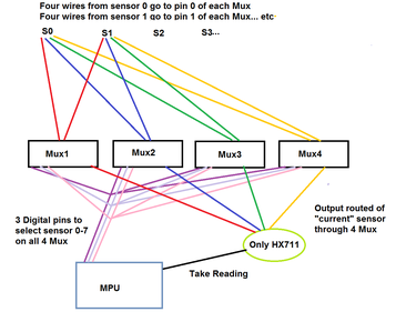
This is the logical connections. Does not show ground wires, capacitor and other misc hookup. Only shows wires coming from 2 of the 8 sensors.
3 lines of code = InqPortal = Complete IoT, App, Web Server w/ GUI Admin Client, WiFi Manager, Drag & Drop File Manager, OTA, Performance Metrics, Web Socket Comms, Easy App API, All running on ESP8266...
Even usable on ESP-01S - Quickest Start Guide
Hi @inq and @fastrunner08,
Would you mind sanity checking my suggestion?
I think that might work if you take care with choice of multiplexer, although I am more doubtful about whether there will be a cost or 'difficulty' saving.
--------
The load cells are fairly low resistance, around 350 Ohms, so introducing multiplexers in series with the energising pair of lines suggests the multiplexers should be chosen for a series resistance that is low compared to 350 Ohms, a reducing the bridge voltage will corresponding output voltage. Not a 'critical' problem, but worth minimising.
Alternatively, we can consider connecting the 4 pairs of energising wires in parallel, directly to the HX711 board, hence halving the multiplexer size (possibly saving two boards) and removing doubts about its resistance. This means the effective resistance to the HX711 module is about 350 / 4 ... just under 90 Ohms.
The data sheet: https://www.digikey.co.uk/htmldatasheets/production/1836471/0/0/1/hx711.html
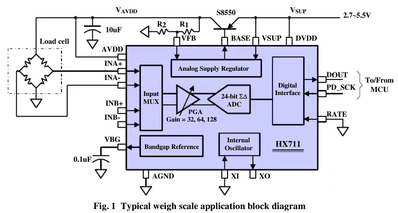
shows a 'typical circuit', including an S8550 transistor, acting as a voltage regulator supplying these energiser lines
Of course, I have no idea what is fitted to a board from Amazon or elsewhere ... it will probably be capable of supplying the 90 Ohm load, but no guarantees ...
This leaves the need for two pole, 4 way multiplexer. I found a chip number that should be capable of providing this function, but finding it on a board may be harder .. & knowing the present chip availability at present, delivery might be 2024 ... I didn't bother looking.
It could be two TCA954A multiplexers, each one providing a single pole, 4 way action, of which an Adafruit version appears in UK Amazon for about £10 each ... lower cost 'unknown' name versions are also listed in Amazon.
------------------------------
Alternatively, UK Amazon also lists a 5 pack of HX711 boards for under £6 including Prime delivery in a couple of days.
So in conclusion, I think Inq's sanity remains intact 😀 😎 , but I still think 4 x HX711 is the easiest choice for the first prototype ...
Obviously, availability and prices depend upon location, but I would guess the story would be similar.
Best wishes and good luck to all, Dave
Alternatively, UK Amazon also lists a 5 pack of HX711 boards for under £6 including Prime delivery in a couple of days.
So in conclusion, I think Inq's sanity remains intact

, but I still think 4 x HX711 is the easiest choice for the first prototype ...
Thank @davee. I didn't double check @fastrunner08 price claim of $10 a piece. He was thinking $80 for the project and Amazon had 10 of the Mux for $2.50. But... if he can get them for that price, I think it's a no brainer. Use KISS principle and buy an amp each.
VBR,
Inq
3 lines of code = InqPortal = Complete IoT, App, Web Server w/ GUI Admin Client, WiFi Manager, Drag & Drop File Manager, OTA, Performance Metrics, Web Socket Comms, Easy App API, All running on ESP8266...
Even usable on ESP-01S - Quickest Start Guide
The mechanics of the situation I have pretty much worked out, the real question I had was around the wiring of them. Does anyone know if it is possible to wire all these in series to one Hx711 or do i need 1 amplifier per load cell.
Already gave you a suggestion. You must have missed it. Look this over:
http://www.gammon.com.au/forum/?id=11976
You get four of these chips... Each chip would handle one wire coming from each of your 8 load cells. It would require 3 digital pins from the Arduino to change which sensor ALL 4 chips are looking at, at any one time. The output (1 wire from each of the 4 chip) would go to the Hx711.
Procedure: Set the 3 data pins to select a sensor, take reading, select the next sensor, take a reading. Daisy chain. Depending on the update rate of the Hx711 would determine how long it would take to read all 8 sensors... probably well under a second.
@davee - Would you mind sanity checking my suggestion?
I looked through your suggested, and ordered the multiplexers to try, however, I don't think that is going to be a viable solution, because multiplexing the readings to the same Hx711 loses the calibration constant for the combination between the Hx711 and the S-bar load cell. I'm sure there is a way to code additional calibration functions so that it changes the constant with each load cell, but as messy as that seems to be, I want to save going down that road as plan b. I pulled my circuits book off the shelf and im refreshing my wheatstone bridge knowledge. Ideally there is a way to combine the signal wires, and then run them into the same amp.
Hey Everyone, I wanted to circle back on this. The solution was much easier that originally thought. For accuracy you do not want to read each load cell individually on a multi-cell system, as that introduces error apparently. The correct way to do it is to put the load cells in parallel with a summation board. The summation board is quite simple, puts the wheat stone bridge in parallel with the others with a trim pot between the +/- so that you can adjust the resistance of each load cell to the same. For what they are buying an off the shelf one is pretty expensive, so I ordered some trim pots 10 ohm, and used my desktop cnc to make my own.
Here is the link to what pointed me in the right direction: https://tacunasystems.com/knowledge-base/load-sell-summing-junction-boxes-signal-trim-and-excitation-trim/
It was a great read, and allowed me to link 8 load cells using only one amplifier and my homemade summation board. I have bench tested they system and it seems to be accurate within 2lbs with a 1000lb load using bags of corn and plywood over the cells on a cement floor. Next step is install them on the gravity wagon, and go from there.
@fastrunner08 Glad you are happy, my only experience with this was when I had my truck and RV weighed one wheel at a a time. Not sure why one works and the other doesn't but as you say you tested it so it's all good.
First computer 1959. Retired from my own computer company 2004.
Hardware - Expert in 1401, and 360, fairly knowledge in PC plus numerous MPU's and MCU's
Major Languages - Machine language, 360 Macro Assembler, Intel Assembler, PL/I and PL1, Pascal, Basic, C plus numerous job control and scripting languages.
Sure you can learn to be a programmer, it will take the same amount of time for me to learn to be a Doctor.
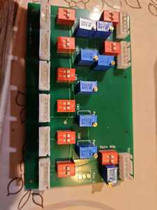
I figured I update on this project. Had some goods and some bads, maybe a few questions mixed in there if anyone wanted to chime in after reading my book of a post. As mentioned before I worked out a combiner board idea for the load cells. I was using supply voltage trimming for the summation method for calibrating the load cells, as it seemed to work better with the Hx711 than signal trimming as some of the fancy combiner boards use. I tried both, but voltage worked better. I made a protoboard the old fashion way to link two cells together. Photos attached. It worked great, I then designed a pcb board for linking 8 together, and had a third party pcb maker make pcb for me. Soldered on all my components and away I went (like a fool) and plugged in all 8 load cells to try it out. Long story short it didn't work, at all. I say like a fool because i didn't check all the traces with the multimeter before plugging everything in and energizing. Turns out the PCB board maker modified my design ever so slightly on a pass through trace circled in the photo. This directly shorted 5v from the amp to the - signal wire going back to the amp and all of the load cells. Long story short (no pun intended) I think i caught it too late. I was able to fix the board with an exacto knife and some nail polish by cutting the shorted trace, but i think I fried all my load cells. Even if i plug them into the amp one at a time i cannot get any readings to stabilize now. If you set tare with no load on one cell plugged to the amp it won't stay even close to 0 it fluctuates from 587lbs to -234lbs at the current calibration setting. If you change the gain/calibration it doesn't matter the reading just bounces all over the place. I had some extra amps and swapped one of those out, but the issue repeats itself. I don't have any additional load cells that where hooked up to shorted board, but I have one on order to test the theory that something electrically in them is toast. I'm pretty bummed, but lesson learned I guess. Unfortunately
it was a very expensive lesson learned as i just fried $400 worth of load cells. I'm still questioning what else I could be missing. Is it really possible to fry a wheatstone bridge with 5-4.2v and the small amount of current the arduino/hx711 amp can put out? Then again there was 4.2v of power going into the - signal wire of the load cell so i'm assuming that is why it cannot give a stable reading now.


