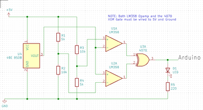
This morning a load of 49E 8508 Hall Effect Sensors arrived through the post. And I thought this may be of use to model railway or possibly robot builders. It is all very well being able to measure magnetic field density but what if you only want to know whether a magnet is near a Hall Effect Sensor. So I came up with the circuit below. This circuit shows if a magnetic source is close to the sensor regardless of the North-South orientation, so it doesn't matter which way you stick your Neodymium magnets to the bottom of your locomotive or whatever else you use it for.
Exerpt form datasheet.
The output pin provides an analog output representing if a magnetic field is present, how strong a present field is, and if it is a north or south polar field. If no magnetic field is present the SS49E will output a voltage around half of the source voltage. If the south pole of a magnet is placed near the labeled side of the SS49E (the side with text etched on it), then the output voltage will linearly ramp up towards the source voltage. The amount of the output voltage increase is proportional to the strength of the magnetic field applied. If the north pole of a magnet is placed near the labeled side of the SS49E then the output voltage will linearly ramp down toward the ground voltage relative to the strength of the magnetic field. For example, if you power the SS49E with 5V and there is no magnetic field present then the sensor's output will be around 2.5V. In the same example, if you place the south pole of a strong magnet near the labeled side of the sensor, then the output voltage will go up to around 4.2V and if you placed the north pole of a strong magnet near the labeled side of the sensor, then the output voltage will drop to around 0.86V.
The Opamps are configured so that Opamp1 will go HIGH if the voltage exceeds 3.3V and Opamp2 will be LOW. If the voltage drops below 1.7V Opamp1 will go LOW and Opamp2 will be HIGH.
The XOR gate handles the rest.
The demo is shown without the XOR gate. I have marked onE end of the magnet blue, this end turns on the green LED and the other end turns on the red LED.
I have attached the schematic in case anybody wants to complete it for a PCB.

