Hi folks, I have built a greenhouse monitoring system using multiple soil moisture probes and a DHT11 sensor. I have it all up and running on my NodeMCU sending the info to Blynk and on to my Smartphone. i am quite happy with the way it all working except for the permanently ON DHT. I have the soil sensors powered off and they are switched via a 22N2222 transistor, left on for 20s before the reading is taken, then switched off again. This is done to reduce power consumption from the battery and also reduce corrosion on the probes.
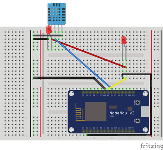
I want to add the DHT to a similar transistor or even Digital pin so it can be powered on, read and powered off. I have a script running on a second NodeMCU on my bench and a circuit wired so that VCC comes from D5 to power the DHT11.
However, when the DHT11 is connected to to D5 it raises the "Failed To Read from DHT11" error. If I make no other changes than simply move the VCC to 3V pin on the NodeMCU, it works fine.
#include "DHT.h"
#define DHTPIN 12     // Digital pin connected to the DHT sensor
#define TRANS D5      // Switch on VCC to DHT or Transistor
#define DHTTYPE DHT11   // DHT 11
DHT dht(DHTPIN, DHTTYPE);

void TransOn()
{
  digitalWrite(TRANS, HIGH);
  dht.begin();
  Serial.println("DHT On");
  delay(2000);
 }

void TransOff()
{
  delay(100);
  digitalWrite(TRANS, LOW);
  Serial.println("DHT Off");
  delay(15000); //delay to next SensorRead run
}


void SensorRead()
{
  Serial.println("DHT Begin");
  Serial.println("Delay 3.5s");
  delay(3500);
  Serial.println("Floats");
  float h = dht.readHumidity();
  float t = dht.readTemperature();
  // Check if any reads failed and exit early (to try again).
  if (isnan(h) || isnan(t)) {
    Serial.println(F("Failed to read from DHT sensor!"));
    Serial.println(h);
    Serial.println(t);
    return;
  }
  Serial.print(F("Humidity: "));
  Serial.print(h);
  Serial.print(F("%  Temperature: "));
  Serial.println(t);
}

void setup() {
 Serial.begin(9600);
 dht.begin();
 pinMode(TRANS, OUTPUT);
 pinMode(DHTPIN, INPUT);
}

void loop()
{
TransOn();
SensorRead();
TransOff();
}
I had a look at a datasheet for the DHT11 and it gave me the impression that maybe some fancy switching is required after power is restored to reset the sensor output to the NodeMCU and provoke it to send data.
Does anyone have any idea if this is the situation I find myself in, and if so, what might the code look like?
Thanks in advance for any pointers received.
Mike
Ooops, I did it again!
Try opening up the sensor in your read function. And at the end, closing it.
Hi folks, I have built a greenhouse monitoring system using multiple soil moisture probes and a DHT11 sensor. I have it all up and running on my NodeMCU sending the info to Blynk and on to my Smartphone. i am quite happy with the way it all working except for the permanently ON DHT. I have the soil sensors powered off and they are switched via a 22N2222 transistor, left on for 20s before the reading is taken, then switched off again. This is done to reduce power consumption from the battery and also reduce corrosion on the probes.
Mike
Hi Mike... I am interested in using several Moisture Probes, etc. also...
Can you describe your Moisture Probes, where to buy, etc. & how they work?
It would be nice if you could write-up your complete application... Might save me a little time from reinventing the wheel. 🙂
Thank you very much!
Have Fun,
Joe Lyddon
www.woodworkstuff.net
@triform I have tried moving dht.begin inside TransON and SensorRead functions but it has no effect.
Ooops, I did it again!
when using a DH11 sensor a 10K resistor is usually used between VCC and the data pin as a pull up as the in built arduino pullups are too weak. As your Fritz diagram does not show this I wonder if this is the cause of your problem.
Ooops, I did it again!
Hi Mike,
I may be reading your fritzing incorrectly as it is very small on my screen. But it looks like you are powering 2 LEDs and the DHT from one of the GIO output. The LEDs also look like they are connect across the GPIO output to ground. If this is how it is set up then you are only getting about 1 volt to the DHT. I don't think the DHT alone can be powered from a GPIO reliably. If you need it I would be happy to provide a simple circuit using a PNP transistor to provide power to you DHT.
Hi @ruplicator and thanks for your input.
In my OP, removing the 2 red LED's does not change the result. I put them there to verify that I was actually getting power where and when I thought I should.
In my full-scale project (my second and larger post above) I have a small red and green LED in the circuit each one powered directly from D0 & D7 respectively. The DHT11 gets its VCC & GND from the 3v bus bar on the right of the breadboard which is in turn powered from an external source (breadboard power supply running from 6v lead-acid battery). The DHT uses pin D7 for its data IO.
The breadboard power supply also powers the 5v bus bar on the left side of the breadboard and this also used to push 5v into the NodeMCU VIN pin and runs the soil moisture modules due to the cable length to the probes. Both bus bars are connected to ground pins on the NodeMCU also. There is a 3rd (yellow) LED which is drawing power from the D8 pin which is used for the transistor too.
I would be very glad to see your diagram of a transistor switching the DHT as every attempt I have made to switch power to the DHT11/22 (including using a 2n2222 similar to that on the Moisture Sensor array) results in it failing to read the T&H. Though if leave everything the same and switch power to the DHT from the bus bar, it works fine.
I hope this helps and look forward to seeing your diagram.
Ooops, I did it again!
You second fritz diagram also appears to lack a 10k resistor I mentioned above, have you tried this?
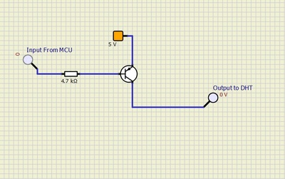
First I'm a little concerned that you are powering the DHT from a 3 volt supply. It's spec sheet says it will work on 3.3V - 5.5V. Even if your supply is 3.3V that leaves no room for us to add a transistor (with its voltage drop) in the power circuit. You indicated that you have a 5V supply available and if you can use it that would be much better. The circuit below uses a PNP transistor rather than your 2N2222 which is an NPN. Almost any PNP transistor will work as you will need very little current to run your DHT. The 4.7K resistor is also not critical critical in this application, just use something close. Also you will need to change your software to output a LOW rather than a HIGH when you want power to be sent to the DHT. One last note: The spec sheet did indicate that the DHT shouldn't be read for at least 1 second after power has been applied and that it might be a good idea to add a 100 nf capacitor to it's input power source.
Data Sheet: https://www.electronicoscaldas.com/datasheet/DHT11_Aosong.pdf
Please disregard my last post. I tried to edit it after I was able to look at your problem more closely but the system wouldn't let.
After looking at you layouts more closely and the spec sheet of the DHT11 the recommendation to switch the power as proposed doesn't seem to be your most probable problem.
1. If your sensor is/will be located away from the processor board the 3.3 V supply may not be adequate for a good signal back to the processor.
2. Some older/cheaper DHT11 sensors don't include a pull-up resistors on the sensor as Byron indicated. If you don't know if yours has this then you will need to include it on the data line.
3. The spec sheet indicates the DHT11 only pulls 1.5 mA maximum during measurement. If this is the case for your unit it may not be worth it to try to switch the power. If you decide you still need to switch the power I think the circuit you are using on on your other sensors should also work fine for the DHT11.
Sorry for the confusion.
@byron Hi and thanks for your thoughts on this. I have added the pullup to the VCC and Data Pin since the fritzing was drawn up and even changed the bare sensor for a DHT module that includes the resistor. The results alas was the same.
Ooops, I did it again!
@ruplicator I have made a boob. The Fritzing for the larger project, as you rightly say, shows the DHT running from 3v. However, on the actual project, I have changed it to the 5v bus bar and not updated my Fritzing Image.
The DHT sensor wiring is about 350mm long so it is not mounted a long way from the project box and I did run the details through my calculator to check it would be OK at that length and that is probably what made me swap it to the 5v rail.
I have tried it with and without the pullup and it is currently running with a DHT11 module which includes the resistor, and again, this made no difference.
I will find a PNP and try it. In all the permutations I have messed with I only used that one transistor type (it's all I have in my box at the moment) so it is definitely worth another mix to see what happens. If I add the DHT11 Module to a similar setup as the soil moisture sensors (2N2222) it powers on fine, but does not read the sensor and instead returns "nan" (Not A Number) as the value for both D and T. I have verified that the sensor is actually on when I think it is, and I have inserted a delay to ensure the sensor is not read in the first 2 seconds to avoid the issue noted on the datasheet. The Chinglish datasheet also gave me the impression that some fancy data pin switching may be required to effectively reset the state of the sensor before it can be read. But it was a difficult read and for a simpleton like me, I may have got the wrong end of the stick.
As for the power saving, that would definitely be something I would like to achieve as the small 6v lead-acid lasts a couple of days and I would like to stretch that as best I can. But as much as anything, it's now also about me wanting to find a solution to the switching on/off issue because I feel I must and don't want to be outsmarted by a little pile of... whatever those things are made out of! If I simply can not find an answer I am considering jumping to a BME280 instead - but I don't like to give up!
Once again, thanks for your thoughts and keep em coming.
Ooops, I did it again!
When you say connecting the DHT11 VCC to the 3V on the NodeMCU makes it work fine, do you mean you can disconnect the 3V and then reconnect it and it works with your code (i.e. after a 3.5 second delay you get correct readings) but does not work when VCC is supplied from the D5 pin (again after a 3.5 second delay)? If so out with the multimeter 😀. But I may have got the wrong end of the probes.


