This project will describe the programming for a two-wheeled differential drive robot. The project will make use of the Robot Operating System (ROS) so the code examples will detail how this can be used. There are two functionality goals for this project. The first is to get it move forward a specified distance, and the second is to have it turn on the spot a certain number of degrees. Although these may seem like simple tasks it does present some programming challenges requiring control feedback loops and PID controllers. The plan is to start with a basic programming model and build it up into a fully autonomous mobile robot.
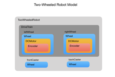
I’ll start by building a program model of a two-wheeled robot to implement its internal functionality, such as driving the wheels and counting encoder pulses. This model won’t include any functionality to control how it gets to its destination. That will be the job of the control loops described later. In the first stage only the drive train is implemented for mobility. Other functionality such as laser and ultrasonic range finders will be added later. The programming model is written using C++ classes but you should be able to translate it into Python, which is the other language widely used with ROS. Here’s a block diagram of the model:
After detailing the two-wheeled robot model I’ll go on to describe the control loops that are used to control the speed, position and orientation of the robot. The position and orientation is known in the ROS world as its “pose”. The outer loop will simply wait to receive a move command that it sends to a control loop to change the robot’s pose.
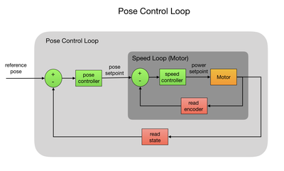
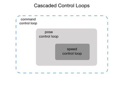
The pose control loop tells the robot how fast it should spin each wheel and this will cascade down to the speed control loop that determines how much power to apply. One of the challenges is to get the robot to go in a straight line. This is not an easy as you may think unless the two motors just happen to be perfect clones of each other. In reality this is never the case, so feedback control must be used to compensate for this. Once the motors are spinning and the robot is moving its position and orientation is tracked so as it can be stopped after it has travelled a certain distance.
Wheeled Robot Kinematics
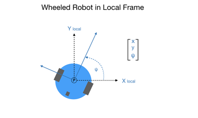
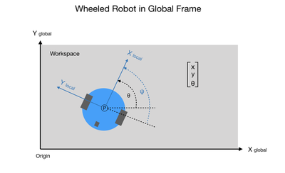
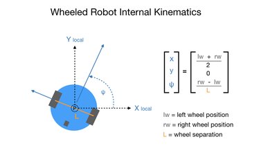
When working with robots the word kinematics comes up a lot. Kinematics simply describes how an object moves. This project will only look at the internal kinematics of the robot, which describes the relationship between its wheel rotation and how it moves. For internal kinematics the robot will move within a local reference frame, as shown in the following diagram.
Note that since the robot has standard fixed wheels that it cannot move sideways. Therefore, the value of the Y component in the internal reference frame will always be zero. Contrast this to external kinematics that describes the robot’s position and orientation relative to a point in a global reference frame, such as a room. In this case, the Y component can be non-zero since we can drive the robot to any location in the room using a series of discrete maneuvers.
Hardware Architecture
The robot has a motor attached to each wheel and is balanced with wheel casters. Each motor has an attached encoder. The compute architecture is very simple at this stage. It uses a single ESP32 micro controller for both the robot’s internal functionality, such as the actuation of its motors, and also its external control where we drive it towards a new position and orientation. Here’s a picture of the rig that I’m using but the program should work with any two-wheeled differential drive robot.
The next few posts will describe the C++ classes that create the two-wheeled robot model.
This is a continuation of the first article on a two-wheeled robot using ROS.
Program Setup
Before we get into the details of the two-wheeled robot model I need to go over the program setup. I included this in an earlier post but I wanted to keep it all in one place. I have ROS installed on a Raspberry Pi with the Ubuntu Mate OS. All of the development is done within the Arduino IDE which includes the ROS library for Arduino plus some ESP32 specific libraries. There are several online tutorials that show you how to setup the Arduino IDE for ROS. In order to connect to ROS you’ll need to specify the network address of the machine on which the ROS server is hosted (the Raspberry Pi in my case) together with the port that it’s listening on. You also have to create a node handle to manage the connection between your control program and the ROS server.
#include

// RaspberryPi host address. Default ROS port is 11411
IPAddress server(192,168,0,ROS_HOST);      // Set the rosserial socket server IP address
const uint16_t serverPort = ROS_PORT;    // Set the rosserial socket server port

// Define the node handle to roscore
ros::NodeHandle nh;
bool nodeHandleCreated = false;
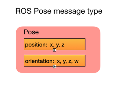
You then include the ROS message type Pose. The format of the Pose message looks like this:
It has two sets of parameters for passing position and orientation. For a wheeled robot you only need to use three of these parameters: position x, y, and orientation y. This will form the command vector for requesting a new reference pose. The reference pose is the final position and orientation that you want the robot to end up in. The pose error vector will hold the difference between the robot’s current pose and its reference pose.
// Include the Pose message
#include <geometry_msgs/Pose.h>

// Define a variable to hold the Pose message
geometry_msgs::Pose pose_msg;

// Subscriber definition
ros::Subscriber<geometry_msgs::Pose> *sub_pose;

// Create matrix to hold the command input
// X position, Y position, Orientation
float refPose[3] = {0.0, 0.0, 0.0};
const byte X_POS = 0;
const byte Y_POS = 1;
const byte PSI = 2;

// Error matrix for feedback loop
float poseError[3] = {0.0, 0.0, 0.0};

// Set callback flag

bool commandCalled = false;
In the setup() you first connect to WiFi. The way in which you do this is dependent on the micro controller that you’re using so I just put a function here. You then initialize and start a node handle that allows you to communicate with the ROS server. The ROS server is a publish/subscribe protocol (basically the ROS version of MQTT). It has a very rich collection of data structures, called messages, that you can use within topics. The Pose message that I described earlier is just one of these message types. A subscribed topic holds the message that your program is interested in. When you subscribe to a topic you need to provide a callback function to process the received message. In my case, the message is a command to move the robot to a new position and orientation. After subscribing to the pose command topic I create an instance of a two-wheeled robot. This is a C++ model that implements all of the functionality of the robot. The code I’m showing here is just the program to control the robot. The model is a work-in-progress and I intend to build on it over time to make it a fully autonomous wheeled robot. Right now it just implements the code for motion control.
//--------------------------------------------//
// Setup
//--------------------------------------------//
void setup() {

// Connect to WiFi
connectWiFi();

// Initialize the ROS nodehandle.
nh.getHardware()->setConnection(server, serverPort);

// Starting node
nh.initNode();
nodeHandleCreated = true;
delay(1000);

// Setup subscriber with callback function to receive the command
sub_pose = new ros::Subscriber<geometry_msgs::Pose>("/pose_cmd", commandCb);
nh.subscribe(*sub_pose);

// Create a robot. Pass the ROS node handle.
robot = new TwoWheeledRobot(&nh);
}
The callback function receives a message to move the robot to a new position and orientation. I’ll go over the callback function in a later article when I document the control loops.
TwoWheeledRobot Class
The model uses C++ classes to represent all of the robot’s components. The following diagram shows how all of these components relate to each other. The two-wheeled robot has a differential drive system, meaning that it has one motor for each wheel. Each of the motors has an optical encoder attached. This is all neatly wrapped up in a drive train. The front and back wheel casters are also represented, but at this stage they don’t serve any function from a programming perspective.
The drive train is used to encapsulate all of the functionality that makes the robot move around. At this stage that’s pretty much all of the robot functionality but we can build on this to add new functionality as the project progresses, such as laser and sonar range finders.
Looking at the code. The TwoWheeledRobot constructor takes in the node handle that’s used to communicate with ROS. The geometry of the robot is defined, which will be useful when we want to avoid obstacles later on. We then attach the drive train that will encapsulate all of our mobility functionality. Finally, the front and back caster wheels are added. The Wheel class takes in the wheel diameter that may not be particularly useful for the caster but will be a crucial part of the odometry when it comes to the powered wheels. The wheel type is also passed in, which is not used right now but I plan to use it later to configure the wheel geometry.
class TwoWheeledRobot
{
public:

// --- Constructor ---
TwoWheeledRobot(ros::NodeHandle * nodeHandle);

// --- Robot configuration ---

// Define the shape and size of the robot
struct Geometry {
uint8_t type = CYLINDER;
float radius = 0.11;
float length = 0.20;
};

// Drive train of robot
DriveTrain driveTrain;

// Unmotorized wheels
const float casterDiameter = 0.020; // caster diameter in meters
Wheel frontCaster = Wheel(casterDiameter, CASTER);
Wheel backCaster = Wheel(casterDiameter, CASTER);
};
The constructor just takes in the ROS node handle for use in publishing the robot’s odometry.
// ----------------------------- Constructor ---------------------
TwoWheeledRobot::TwoWheeledRobot(ros::NodeHandle * nodeHandle)
:driveTrain(nodeHandle)
{
}
DriveTrain Class
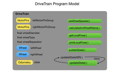
The DriveTrain class encapsulates all of the robot’s mobility functionality. The following diagram shows the drive train configuration parameters on the left and its control functions on the right.
The first thing to explain is the motor pinGroup. The pinGroup is a structure of GPIO pins that are used to attach the motors and encoders to the micro controller. There are three pins for the motor, two to control the direction and one for the PWM signal that applies the power. The encoder A and B pins are used to control a quadrature encoder. The pins are grouped so as we can easily reference them together depending on the motor we are controlling. I have this structure in a configuration file to extract it from the DriveTrain class.
// Define the GPIO pins for the motors
static struct DRAM_ATTR MotorPins {
const byte motorDir1; // motor direction pin1
const byte motorDir2; // motor direction pin2
const byte enable; // Enable PMW
const byte encoderA; // encoder channel A
const byte encoderB; // encoder channel B
} motorPinGroup[2] = {27, 26, 25, 36, 37,
14, 12, 13, 38, 39};
Since the DriveTrain class has two wheels I assign a pinGroup number to the left and right wheels. The wheel diameter and type is also defined, which we pass to the Wheel class constructor to create each wheel. We also want to know how far apart the wheels are since this is critical to calculating path trajectory.
class DriveTrain
{
public:

// Constructor
DriveTrain(ros::NodeHandle * nodeHandle);

uint8_t leftWheelPinGroup = 0; // GPIO pin group config.h
uint8_t rightWheelPinGroup = 1; // GPIO pin group config.h

const float wheelDiameter = 0.063; // wheel diameter in meters
const uint8_t wheelType = STANDARD_FIXED;
const float wheelSeparation = 0.179; // wheel separation in meters

Wheel leftWheel = Wheel(leftWheelPinGroup, wheelDiameter, wheelType);
Wheel rightWheel = Wheel(rightWheelPinGroup, wheelDiameter, wheelType);
The DriveTrain is responsible for keeping track of the current position and orientation state of the robot. The ROS message type Odometry is used for this purpose. The node handle is used to connect to the ROS server so as we can publish the current state of the robot. This is used by the control loop that drives the robot to its requested pose.
// Pointer to the ROS node
ros::NodeHandle * nh_;

// Robot state
nav_msgs::Odometry state;

// Define publisher for ROS
ros::Publisher* pub_odom;
The constructor initializes the robot’s state variables that track the robot’s position, orientation, and velocity. The publisher is also initialized to write the Odometry state out to the ROS server. Finally a periodic timer is started to update the robot’s state every 50 milliseconds.
// ------------------ Constructor ---------------------------------
DriveTrain::DriveTrain(ros::NodeHandle * nodeHandle)
:nh_(nodeHandle)
{
// Attach robot to the global odometry frame
state.header.frame_id = "/odom"; // Global odometry frame
state.child_frame_id = "/base_link"; // Robot local frame

// Setup publisher to report current state
pub_odom = new ros::Publisher("/odom", &state);
nh_->advertise(*pub_odom);

// Start state update timer
const esp_timer_create_args_t periodic_timer_args = {.callback = &updateStateISR};
esp_timer_create(&periodic_timer_args, &stateUpdateTimer);
esp_timer_start_periodic(stateUpdateTimer, updatePeriodMicros); // Time in milliseconds (50)
instances[0] = this;
}
In the next article I'll explain how to set the wheel speeds and update the robot’s state. Updating the state requires some understanding of wheeled robot kinematics. I’ll also document how the state is published to ROS.
This is part 3 of the two-wheeled robot project using ROS. In this post I'll continue to look at the DriveTrain class. The main tasks of the drive train is to set the speed of its wheels, and to report out its current pose state. For wheeled robots this is commonly referred to as odometry. The pose state is updated 20 times a second using a timer interrupt routine. Functions to get the local pose and velocity are pretty self explanatory. They simply return the vectors for those states. I’ll start with the wheel speed control.
//--- Drive train functions ---
void setWheelSpeeds(float leftWheelSpeed, float rightWheelSpeed);

void publishState();

float * getLocalPose();

float * getLocalVelocity();

void printLocalPose();

private:
// --- Odometry state variables and methods ---

// Keeps track of encoder pulses from each wheel
uint32_t leftPositionLast_ = 0, rightPositionLast_ = 0;
const int maxPulsesPerSecond_ = 600;

static DriveTrain * instances [1];

// Static instance to update robot state
static void updateStateISR(void *pArg)
{
if (DriveTrain::instances[0] != NULL)
DriveTrain::instances[0]->updateState_();
}

// Instance member to update robot state. Called from updateStateISR
void updateState_();
};
Wheel Speed Control
Setting the wheel speed is undoubtedly the most important control function for the DriveTrain. The wheel speed is passed in as a ratio between -1 and +1, where a negative value would send the robot backwards and a positive value moves it forward. Zero would stop the motor. The motor however, only understands pulses per second for its control parameter, so we have to translate from the speed ratio to a pulse per second rate. For example, if our maximum pulses per second is say 600 then that would represent a speed ratio of 1.0 forward or -1.0 backwards. To reduce the speed we send in a fractional value, 0.5 for example. This would cut our pulses per second down to 300. This should all make more sense when we look at the motor and encoder models.
// -----------------------------------------------------------------
// Set the left and right wheel speeds
// Input is a speed ratio between -1.0 (backwards) and 1.0 (forward)
// Output is a wheel speed in pulses per/sec
// -----------------------------------------------------------------
void DriveTrain::setWheelSpeeds(float leftWheelSpeed, float rightWheelSpeed) {

  // Translate the speed ratio into pulses per/sec.
  // Where speed ratio of 1.0 equals 600 pulses per/sec
  int leftPulseSetpoint = int(maxPulsesPerSecond_ * leftWheelSpeed);
  int rightPulseSetpoint = int(maxPulsesPerSecond_ * rightWheelSpeed);

  leftWheel.setSpeed(leftPulseSetpoint); // Pulses per/sec
  rightWheel.setSpeed(rightPulseSetpoint); // Pulses per/sec
}
Odometry
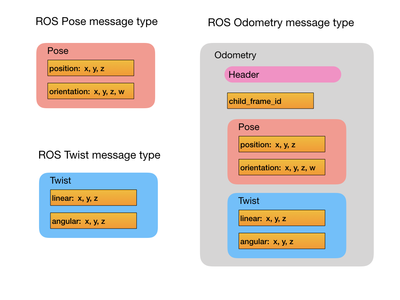
Another function of the DriveTrain is to continuously update the robot’s odometry state and publish it to the outside world. For this we use the ROS Odometry message type which is shown in the following diagram. The Pose part of the message is the same as we saw earlier. What’s been added is the Twist message that holds the linear and angular velocity. The child_frame_id points to the robot itself and is usually called the base_link. This is connected to the Odometry frame via the header. This allows us to track the robot within a global frame.
The following diagram shows the difference between the local (internal kinematic) frame and the global (external kinematic) frame, referred to as the Odometry frame when dealing with wheeled robots. Notice that the symbol for orientation has change from ψ (psi) to θ (theta) when we go from the local frame to the global frame.
The following code shows how the Odometry message is published to ROS for a wheeled robot. Not all of the data variables are used since we’re only working on a 2D plane. If this were a drone then all of the variables would be used. A project note here is that at this stage I’m reporting out the robot’s local pose instead of its global pose. For an Odometry message this should actually be tracking the X, Y, theta location within a workspace (your living room). I’ll switch to the global frame later in the project. See the next section for more on this.
// ------------------------------------------------------
// Publish current robot state to ROS
// ------------------------------------------------------
void DriveTrain::publishState() {

  // Add the timestamp
  state.header.stamp = nh_->now();

  state.pose.pose.position.x = local_pose[X_POS];
  state.pose.pose.position.y = local_pose[Y_POS]; // zero since cannot move sideways
  state.pose.pose.orientation.y = local_pose[PSI]; // theta

  state.twist.twist.linear.x = local_velocity[X_VELOCITY];
  state.twist.twist.linear.y = local_velocity[Y_VELOCITY];  // Can't move instantaniously sideways
  state.twist.twist.angular.y = local_velocity[Y_ANGULAR]; // angular yaw velocity in radians

  // Publish
  pub_odom->publish( &state );
}
Updating the state requires some understanding of wheeled robot kinematics.
Internal Kinematics
Internal kinematics describes the relationship between a system’s internal variables and its motion. In the case of a wheeled robot our internal variables would be its wheels, which can rotate and cause motion, assuming that they are in contact with the ground. For a differential drive robot each wheel can move at a different speed, therefore we need to look at how each wheel contributes to the robot’s overall motion. When we’re dealing with internal kinematics we can describe its movement in terms of a local frame. In the robot’s local frame forward motion is indicated by the X direction. To get its total movement in the X direction we can simply add the distance covered by each wheel and divide the result by 2.
So what about the Y direction? If we had a Swedish wheel, also known as a Mecanum wheel, it would be able to move in any direction. However, for this project I’m using standard wheels that can only roll in the direction of their orientation. Therefore, its movement in the Y direction is always going to be zero. This is referred to as a kinematic constraint. We’re constrained to not move in the Y direction.
The orientation is the angle measured from the X-axis of the local frame to the forward orientation of the robot. So when we first start out the value of ψ would be 0.0, meaning that the robot would be aligned with its own local X-axis. In the local frame there is no notion of coordinates such as east and west or front and back of building. Those coordinate frames will be mapped to when we consider external kinematics. In order to rotate the robot each wheel would need to move at a different speed therefore covering a different distance. To compute the rotation you would subtract the left wheel distance from the right wheel distance and divide it by the length of the wheelbase. The following diagram summarizes all of this.
Update State
Implementing the robot’s kinematics in code would look like the following. The left and right wheel positions are obtained from the Wheel class. This is the distance travelled since the robot was switched on. The calculated pose is put into a pose vector. I named the vector local_pose since the calculated pose is in the robot’s local frame. The velocity is also calculated and placed in the velocity vector. This process is called every 50 milliseconds.
// ------------------------------------------------------
// Update the current robot state
// ------------------------------------------------------
void DriveTrain::updateState_() {

  // --- Get the distance delta since the last period ---
  float leftPosition = leftWheel.currentPosition();
  float rightPosition = rightWheel.currentPosition();

  // --- Update the local position and orientation ---
  local_pose[X_POS] = (leftPosition + rightPosition) / 2.0; // distance in X direction
  local_pose[Y_POS] = 0.0; // distance in Y direction
  local_pose[PSI] = (rightPosition - leftPosition) / wheelSeparation; // Change in orientation

  // --- Update the velocity ---
  float leftDistance = (leftPosition - leftPositionLast_);
  float rightDistance = (rightPosition - rightPositionLast_);
  float delta_distance = (leftDistance + rightDistance) / 2.0;
  float delta_theta = (rightDistance - leftDistance) / wheelSeparation; // in radians

  local_velocity[X_VELOCITY] = delta_distance / updatePeriodMicros; // Linear x velocity
  local_velocity[Y_VELOCITY] = 0.0;
  local_velocity[Y_ANGULAR] = (delta_theta / updatePeriodMicros); // In radians per/sec

  // ---  Save the last position values ---
  leftPositionLast_ = leftPosition;
  rightPositionLast_ = rightPosition;
}
The pose and velocity are available in vector form, which is made use of in the control loops. For debugging purposes it can also be useful to print the pose out to the ROS console. This is akin to printing to the serial port except that you don’t need to attach the robot to a really long USB cable. You can also echo the published Odometry message out to the Linux terminal. The published message can be recorded for later playback in a simulator.
 // ------------------------------------------------------
// Returns the local robot state
// ------------------------------------------------------
float * DriveTrain::getLocalPose() {
  return local_pose;
}

// ---------------------------------------------------
// Return local robot velocity of robot in meters/sec
// ---------------------------------------------------
float * DriveTrain::getLocalVelocity() {
  return local_velocity;
}

// ------------------------------------------------------
// Returns the local robot state
// ------------------------------------------------------
void DriveTrain::printLocalPose() {
  ROSLOGString("Local pose X, Y, Psi");
  ROSLOG3F(local_pose[X_POS], local_pose[Y_POS], local_pose[PSI]);
}
That’s it for now. The next post will look at the Wheel, DCMotor, and Encoder classes.
@mjwhite Very nice article indeed. I feel like I'm reading Popular Robotics magazine. I hate to even post here and contaminate the article, but I felt that some comments of appreciation are in order. Your work is very much appreciated. Thank you.
DroneBot Workshop Robotics Engineer
James
Please post replies to any of the articles. My hope is to get comments and ideas that will help improve the software. The posts here are just the first phase of the project. My goal is to build this into a fully autonomous mobile robot, so there are many programming challenges ahead. I'm going to need all the help I can get.
Without having a robot system up and running that is similar to the one you are working on I'm afraid I don't have the time to invest in paying attention to all the details. I'm reading your articles just to get a general idea of what you are doing. I glance over your code just to get a feel for what you are doing. But I'm not putting nearly the attention to detail that would be required to make any suggestions. I would need to actually be working on the same robot system you are working with before it would be worth my investment of time to get into those kind of details. I would love for that to be the case. But alas without the robot system to actually work with it's just not going to happen.
I'm currently working on a couple two-wheeled robots right now, but unfortunately I don't even have them up to the point where they are fully functional. In fact, for the past couple weeks I've been trying to find the time to take photos of them and post them in the robot projects section. I can't even seem to make time for that. Unfortunately robotics is just a hobby for me, and real life has been kind of greedy in wanting to take up all my hobby time lately.
I hope you keep posting your articles. Just know that they are being read, and I may come back at a future date and see if I can implement some of what you are doing into my robot projects. Not sure if that will happen before late fall or early winter though. I get pretty busy during the summer and fall with real life distractions.
DroneBot Workshop Robotics Engineer
James
This is part 4 or the two-wheeled robot project using ROS. In this post I’ll detail the Wheel, DCMotor, and Encoder classes, which will complete the robot model piece of the project.
Wheel Class
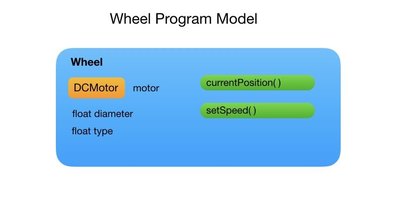
A wheel has several properties probably the most important of which is its diameter and whether or not it is powered. To understand the wheel’s kinematic constraints we’d also need to know whether it is fixed or steerable, and whether it’s holonomic or nonholonomic. A holonomic wheel, such as an Mecanum wheel, is able to move instantaneously in any direction. The Wheel class needs to encapsulate all of these properties. In the following diagram the wheel’s configuration is shown on the left and the functions are listed on the right.
Wheel Configuration
The Wheel class keeps track of the wheel diameter and a wheel type. The wheel type lets us understand the kinematic constraints of the robot. For instance, a Mecanum wheel will allow the robot to move instantaneously in any direction whereas a fixed wheel would only allow movement in a straight line. If the wheel is powered then it will also add a DCMotor object. Here’s a list of possible wheel types that we may what to represent in the Wheel class.
 // Define wheel types
enum WheelTypes {
  STANDARD_FIXED = 1,
  STANDARD_FIXED_POWERED,
  STANDARD_FIXED_CONNECTED,
  STANDARD_FIXED_CONNECTED_POWERED,
  STANDARD_STEERABLE,
  STANDARD_STEERABLE_CONNECTED,
  CASTER,
  SWEDISH,
  MECANUM,
  SPHERIC
};
As a programming note, I currently don’t use the wheel types to make any decisions in the code. I could for instance pass in one of the powered wheel types that tells the Wheel class to create a DCMotor object. Right now I have a class constructor for each type of wheel, powered or unpowered. I’m planning on enhancing the class to use the wheel type attribute at a later point.
The Code
There are two constructors in the Wheel class. One is for a powered wheel and the other is for an unpowered wheel. Both constructors accept the wheel diameter and wheel type parameters. The currentPosition() function computes the distance travelled since the robot was started. The setSpeed() function just passes the speed setpoint onto the DCMotor class.
class Wheel
{
  public:
    // Constructor for powered wheels
    Wheel(uint8_t pinGroup, float wheelDiameter, uint8_t wheelType);

    // Constructor for unpowered wheels
    Wheel(float wheelDiameter, uint8_t wheelType);

    // -------------------- Member variables -----------------

    // --- Configuration (physical) properties ---
    float diameter; // wheel diameter in meters
    uint8_t type;

    DCMotor motor;

    // ---  Kinematic (motion) properties ----
    const float distancePerPulse = (PI * diameter) / Encoder::PPR;   // PI*D/PPR

    // Current direction of the wheel
    int currentDirection = 0;

    // Get the current linear_x position of the wheel
    float currentPosition();

    // ------------------- Convenience methods ------------------

    // Set wheel speed in meters/sec
    void setSpeed(float speed);

    // Encoder pulses from attached motor
    int32_t encoderPulses();
};
When a powered wheel is created a pinGroup is passed in and used to create the DCMotor object. I went into more detail about pinGroups in a previous post. This parameter is not needed for an unpowered wheel.
// ------------------ Constructors --------------------------
// This is for a powered wheel so we need a motor and a set of GPIO pins to connect
// it to the microcontroller.
Wheel::Wheel(uint8_t pinGroup, float wheelDiameter, uint8_t wheelType)
  :motor(pinGroup), diameter(wheelDiameter), type(wheelType)
{
}

// This is for an unpowered wheel so no motor gets attached.
Wheel::Wheel(float wheelDiameter, uint8_t wheelType)
  :diameter(wheelDiameter), type(wheelType)
{
}
Wheel State
It would be useful to know how far the wheel has travelled since we turned the robot on. This information is returned by the wheel’s currentPosition() function. We need to translate the number of encoder pulses into a distance travelled. For that we take our wheel diameter multiplied by Pi and divide that by the number of encoder pulses per revolution to come up with a distance per encoder pulse. Multiplying distancePerPulse by the total number of pulses since the robot started gives us our current X position.
// ---------------------------------------------------
// Get wheel position in meters
// ---------------------------------------------------
float Wheel::currentPosition() {
return motor.encoder.pulses * distancePerPulse;
}
DCMotor Class
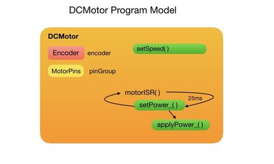
The robot uses DC motors to actuate the wheels. The DCMotor class includes the motor’s configuration together the functions to control it. In the following diagram the configuration is shown on the left and the motor control functions are listed on the right.
Motor Configuration
The pinGroup is passed in from the DriveTrain class and is used to associate the motor with the micro controller’s GPIO pins. The attached wheel encoder is implemented by the Encoder class. In order to control the motor speed a periodic timer interrupt is used. The timers are implemented with static class methods since we cannot use interrupts within member functions. For the two-wheeled robot I have created two instances of the static timer function, one for each wheel. Each instance is referred to by its pinGroup number. The following code shows the configuration of the DC motor.
class DCMotor
{
  public:

    DCMotor() {} // Default constructor

    // Constructor to connect motor GPIO pins to microcontroller
    DCMotor(uint8_t pinGroup);

    // Encoder attached to the motor
    Encoder encoder;

    // Set the wheel speed
    void setSpeed(float pulseSetpoint);

  private:

    uint8_t pinGroup_; // motor GPIO pins

    static DCMotor * instances [2];

    // Encoder interrupt routines
    static void motorISR0 (void *pArg)
    {
      if (DCMotor::instances [0] != NULL)
        DCMotor::instances [0]->setPower_();
    }

    static void motorISR1 (void *pArg)
    {
      if (DCMotor::instances [1] != NULL)
        DCMotor::instances [1]->setPower_();
    }

    // Motor speed variables
    int32_t pulsesLast_ = 0;
    int32_t pulsesPerSec_ = 0;
    int error_ = 0;
    float pPart_ = 0.0, iPart_ = 0.0; // PI control
    int PWM_ = 0; // Current PWM
    int pulseSetpoint_ = 0; // Current pulse setpoint

    // PI control. Adjust gain constants as necessary.
    const float Kp = 0.1, Ki = 0.1; // gain constants

    // Set motor power
    void IRAM_ATTR setPower_();

    // Apply power to the motor
    void IRAM_ATTR applyPower_(int dir, int PWM);
};
The constructor uses the pinGroup that it got from the DriveTrain in order to attach its encoder. The pinGroup is also saved in the DCMotor class for later use. The motor direction and PWM pins are associated with the micro controller. The setup of the PWM pin varies depending on the architecture of the micro controller, so I have abstracted into its own hardware specific function. A static timer interrupt is created depending on the pinGroup. The callback function for each interrupt can be seen in our DCMotor class declaration.
 // -------------------Constructors -----------------------------------
DCMotor::DCMotor(uint8_t pinGroup)
  :encoder(pinGroup), pinGroup_(pinGroup)
{
  // Connect motor to GPIO pins
  pinMode(motorPinGroup[pinGroup].motorDir1, OUTPUT); // motor direction
  pinMode(motorPinGroup[pinGroup].motorDir2, OUTPUT); // motor direction
  pinMode(motorPinGroup[pinGroup].enable, OUTPUT);

  // Setup PWM signal
  ledcSetup(pinGroup_, freq, resolution); // create a PWM channel
  ledcAttachPin(motorPinGroup[pinGroup_].enable, pinGroup_); // attach channel to pin

  // Start motor power timers
  switch (pinGroup)
  {
  case 0:
    {
      const esp_timer_create_args_t periodic_timer_args = {.callback = &motorISR0};
      esp_timer_create(&periodic_timer_args, &motorTimer0);
      esp_timer_start_periodic(motorTimer0, speedCtrlPeriodMicros); // Time in milliseconds (50)
      instances [0] = this;
    }
    break;

  case 1:
    {
      const esp_timer_create_args_t periodic_timer_args = {.callback = &motorISR1};
      esp_timer_create(&periodic_timer_args, &motorTimer1);
      esp_timer_start_periodic(motorTimer1, speedCtrlPeriodMicros); // Time in milliseconds (50)
      instances [1] = this;
    }
    break;

  } // end of switch
}
Motor Speed Control
The first thing we’d want to do is set the speed of the motor. Our motor speed depends greatly on how much load its under. When you look at the specifications of a motor you’ll find its No-load Speed. This is how fast the motor will run if you applied full power and held it in the air. There’s nothing slowing the motor down like the weight of a robot chassis. It’s under no load. On our real world robot however, the speed of the motor will depend on such factors as the weight of the robot, whether it’s going up or down hill, and what type of surface it’s running on. This makes our task of controlling the speed much more difficult.
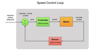
So to make sure that the robot runs at a set speed under all of these conditions we’ll need to control the amount of power that’s applied to the motor. For that we can implement a control loop. Let’s say that our goal is to have the robot move at 1/2 meter per second. We’ll direct the controller to apply a certain amount of power to the motors. We’ll observe how fast the robot is moving using the wheel encoders (sensor). If our robot is moving too slowly then we’ll apply more power. If it’s moving too fast then we apply less power. The difference between the required speed and the actual speed is our error. This is done in a continuous loop while the robot is moving. The control loop is shown below.
Within the speed control loop we check how fast the motor is spinning at each instant of time and adjust the power accordingly. We count the number encoder pulses per second and make sure that we maintain the required pulse rate by adjusting the power. There’s more information about encoder pulses later in the post. Since the motor really only cares about encoder pulses it doesn’t need know about the translational speed of the robot so we just need to give it a pulse rate and let it track against that.
// --------------------------------------------------------
// Sets the local pulseSetpoint which is picked up in the
// setPower_() periodic timer. This will give pulses between
// 60 and 600.  600 pulses per/sec is about 35 cm/sec
// --------------------------------------------------------
void DCMotor::setSpeed(float pulseSetpoint) {

  // PulseSetpoint drives the action of the setPower_() routine
  pulseSetpoint_ = pulseSetpoint;
  encoder.wheelDirection = sgn(pulseSetpoint);
}
When we created the DCMotor object it launched a periodic timer that executes the setPower() function. In the example I’ve set the frequency to 25 milliseconds, so it will execute the setPower() function 40 times per second.
PID Control
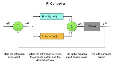
A PID controller is a control loop feedback mechanism that calculates the difference (error) between a desired setpoint and the actual output from a process. If the error value is non-zero then it applies a correction to process input. PID stands for Proportional, Integral, Derivative. For the motor control process I’ve found that I only needed the PI part of the mechanism so I wrote a few simple lines of code to implement it. There’s a very well documented Arduino library that provides a full implementation of a PID controller. The diagram below shows a generalized PI control flow. In our motor control case, r(t) would be the required encoder pulses per second and e(t) would be the difference between the current pulses coming from the encoder y(t) and the required pulses. The motor input PWM signal is represented by u(t). Kp and Ki are tunable parameters that provide the proportional and integral gain value constants for the controller.
The Code
The first step is to get the number of encoder pulses since the last time period and multiply it by the periods per second. This gives us the number of pulses per second which can then be used by the PI controller. The PI controller calculates the error between the current pulses and the required pulses and resets the value of the PWM signal. For my robot I’ve found the following controller gain constants to be reasonable. You can play around with these to get the optimal values for your situation. For the proportional part the control gain should be quite a bit less than one otherwise you would get a very large value for the PWM signal. This would cause a sudden jolt as the robot starts up. The integral part should be adjusted so as you don’t keep oscillating around the setpoint value. Ok, maybe I should write a separate article on this?
There’s a situation where the integral part of the calculation drops below zero as the motor shuts down. This results in a negative PWM signal that I’ve taken care of in the code. Once the new PWM value is computed I figure out what direction the motor is going in and execute the applyPower() function.
void IRAM_ATTR DCMotor::setPower_() {

  // Get the number of pulses since the last period
  int32_t pulses = encoder.pulses;
  int32_t pulsesThisPeriod = abs(pulses - pulsesLast_);

  // Save the last pulses
  pulsesLast_ = pulses;

  // Compute the error between requested pulses/sec and actual pulses/sec
  pulsesPerSec_ = pulsesThisPeriod * periodsPerSec;
  error_ = abs(pulseSetpoint_) - pulsesPerSec_;

  // --- PI control ---
  pPart_ = Kp * error_; // Proportional
  iPart_ += Ki * error_; // Integral

  // We've put the setpoint to zero, stopping the motors
  if (iPart_ < 0.0) {
    iPart_ = 0.0; // Don't let integral part go negative
  }

  // Compute the PWM
  PWM_ = int(pPart_ + iPart_);

  // Motors are shutting down
  if (pulseSetpoint_ == 0 && iPart_ == 0.0) {
    PWM_ = 0;
  }

  // Apply the power with the direction and PWM signal
  applyPower_(sgn(pulseSetpoint_), PWM_);
}
The applyPower() function sets the direction of the motor and writes the PWM signal to the motor’s enable pin. Writing the PWM signal may be different depending on the hardware so I’ve abstracted it out into a separate function. On the Arduino platform it’s a simple analogWrite function. On the ESP32 it’s a little more complicated.
// ------------------------------------------------
// Apply power to motor
// ------------------------------------------------
void IRAM_ATTR DCMotor::applyPower_(int dir, int PWM) {

  int level;
  if(dir >= 0) {
    level = HIGH;
  } else {
    level = LOW;
  }

  digitalWrite(motorPinGroup[pinGroup_].motorDir2, level); // Direction HIGH forward, LOW backward
  digitalWrite(motorPinGroup[pinGroup_].motorDir1, (!level)); // Write the opposite value

  // See setupPWM(pinGroup) in Config.h
  ledcWrite(pinGroup_, abs(PWM));
}
Encoder Class
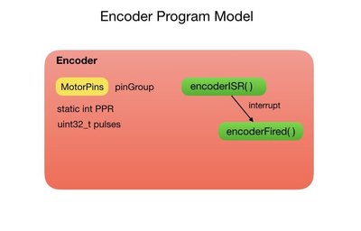
The robot has an optical encoder attached to each wheel. The pinGroup is a structure of GPIO pins that are used to attach the encoders to the micro controller. The PPR variable stands for Pulses Per Revolution. This is the number of pulses that the encoder generates for each revolution of its motor. In my case there are 341 pulses per revolution. The pulses variable tracks the number of encoder pulses since we started the robot and is incremented via a hardware interrupt.
The Code
Since we can’t use a member function for an interrupt in C++ the Encoder class sets up a static function for each interrupt. This is not an ideal situation since we can’t just create additional encoder objects without adding more functions. The interrupt will increment or decrement the pulses variable depending on whether the motor is moving forward or backwards.
 class Encoder
{
   public:

    // Class variables
    static const int PPR = 341;  // Encoder Count per Revolutions

    // Default constructor
    Encoder() {}

    // Constructor to connect encoder GPIO pins to microcontroller
    Encoder(uint8_t pinGroup);

    volatile int32_t pulses;
    int8_t wheelDirection = 0;

    static Encoder * instances [2];

  private:

    uint8_t pinGroup_;

    // Encoder interrupt routines
    static void encoderISR0 ()
    {
      if (Encoder::instances [0] != NULL)
        Encoder::instances [0]->encoderFired_();
    }

    static void encoderISR1 ()
    {
      if (Encoder::instances [1] != NULL)
        Encoder::instances [1]->encoderFired_();
    }

    // Checks encoder A
    void IRAM_ATTR encoderFired_();
};
In the constructor we setup an interrupt using the encoder A and B pins of the motor pinGroup. I’m using a quadrature encoder, hence the need for channels A and B. The interrupts get attached depending on whether it’s the left or right encoder. The interrupt will fire as the GPIO pin goes from low too high. The instances array is assigned a pointer to the member that we just created.
// ---------------------  Constructors -------------------------------
Encoder::Encoder(uint8_t pinGroup)
  :pinGroup_(pinGroup)
{
  // Connect encoder to GPIO pins
  pinMode(motorPinGroup[pinGroup].encoderA, INPUT); //  Left encoder, channel A
  digitalWrite(motorPinGroup[pinGroup].encoderA, HIGH); // turn on pullup resistors
  pinMode(motorPinGroup[pinGroup].encoderB, INPUT); //  Left encoder, channel B
  digitalWrite(motorPinGroup[pinGroup].encoderB, HIGH); // turn on pullup resistors

  // Attach interrupts
  switch (pinGroup)
  {
  case 0:
    attachInterrupt (motorPinGroup[0].encoderB, encoderISR0, RISING);  // Left encoder
    instances [0] = this;
    break;

  case 1:
    attachInterrupt (motorPinGroup[1].encoderA, encoderISR1, RISING); // Right encoder
    instances [1] = this;
    break;

  } // end of switch

  // Switch on interrupts
  sei();
  // Initialize pulses.
  pulses = 0;
}
So one of the reasons for using a quadrature encoder is that it can detect which direction the motor is spinning by tracing the offset between channels A and B. I wasn’t able to get this working on the ESP32 for some reason so I just used a variable to determine whether the pulses should be incremented of decremented. I’ll probably try and get this working at some point. Since the pulses variable is four bytes long the mutex is used to ensure that the increment and decrement occurs as an atomic operation.
 void IRAM_ATTR Encoder::encoderFired_() {
  // pulses is 4 bytes so make sure that the write is not interupted
  portENTER_CRITICAL_ISR(&timerMux);

  if (wheelDirection > 0) {
    pulses++;
  } else {
    pulses--;
  }
  portEXIT_CRITICAL_ISR(&timerMux);
}
That completes the two-wheeled robot model for now. There will probably be other additions to the model as more capabilities are added to the project. The next post will detail the control loops that move the robot in a straight line and rotate it on the spot.
Thank You for a very detailed description. But, sadly, I'm not very bright, so I have a few dumb questions
1) How did you manage to get ROS installed on a pi ? I've tried numerous times and it gets 95% finished then tells me that it can't find a final repository. I even found a few prebuilt images that, once loaded, wouldn't update because it couldn't find the repository that it supposedly needed in order to be installed in the first place
2) If the ROS-pi is the publisher, do you have an esp8266 (or something like it) on an arduino as the subscriber ? (you said to connect to the network address of the ros)
And then the arduino would send the signals to the motor controller ? (md10c or l298n or something)
3) You covered encoders in the motors. The motors that @Bill picked up for DB1 have built in hall type encoders (I ordered the same ones. In fact, I ordered most of the same parts so I could use whatever code he finally publishes) If the arduino is only a subscriber, what happens to the data from the encoder ? It looks like you're saying that it goes back to the pi, but, it also looks like you're saying that it goes to the microcontroller
I can help you with the first question
'Couldn't find the repository' must qualify as one of the top 10 least helpful error messages of all time. In this case it usually means that there is a problem with the repository key. A couple of months ago ROS had an issue with their key so they issued a new key. Very few tutorial have been updated to reflect the new key.
I usually follow the instruction found at http://wiki.ros.org/ROS/Installation click on the version of ROS you want to use. Then select Debian to get the key for the Debian/raspian release.
Updating the documentation, what a novel idea
Somebody should suggest that to them
I will give the wiki addy you posted a shot. Thank you
Please let us know how it goes. If you have any trouble I'll write an installing ROS on Raspian script and upload it to git hub.
Getting used to the ROS community takes a little time if you are used to working with Linux or other open source project with a GPL license. Those projects, including the documentation, tend to be very collaborative.
ROS uses a different open source license call BSD. It feels more like people just throw their code out into the wide and forget about once they have written their paper or completed a project.
I can see why universities and the manufactures who fund research like BSD, but is has taken me a while to get used to it.
Thanks for addressing the first question twobits. I didn't come across that error so I would have been struggling on it.
2) If the ROS-pi is the publisher, do you have an esp8266 (or something like it) on an arduino as the subscriber ? (you said to connect to the network address of the ros)
And then the arduino would send the signals to the motor controller ? (md10c or l298n or something)
The message is published from the command line on the Pi. It takes the form of:
rostopic pub -1 /pose_cmd geometry_msgs/Pose '{position: {x: 1.0, y: 0.0, z: 0.0}, orientation: {x: 0.0,y: 0.0,z: 0.0, w: 0.0}}'
where 1.o requests a one meter change in the X position of the robot. I have an ESP32 running the robot code that is subscribing to the Pose message sent from the Pi. The Raspberry Pi runs the roscore server process which acts as the publish/subscribe exchange. This is the network address of ROS that I refer to.
The motors are actuated through an L298N in my case.
3) You covered encoders in the motors. The motors that @Bill picked up for DB1 have built in hall type encoders (I ordered the same ones. In fact, I ordered most of the same parts so I could use whatever code he finally publishes) If the arduino is only a subscriber, what happens to the data from the encoder ? It looks like you're saying that it goes back to the pi, but, it also looks like you're saying that it goes to the microcontroller
The data from the encoders is used to control the motor speeds. This is done in the DCMotor::setPower() function. It's also used to compute the new position of the robot that is subsequently published to the ROS server. At this point I don't do anything with the published data other than to view it in a charting tool for debugging. The published output can also be captured in a file that ROS calls a bag. It can then be played back in RVIS which is a ROS visualization tool.
I hope this answers your questions. Please let me know if there's anything else.
This is the final part of the two-wheeled robot project using ROS. The first four posts of this topic described the programming model of the robot. In this post I’ll show the control loops that drive the robot to its requested destination and orientation. The control loops are arranged in cascaded fashion where the outer command loop calls the pose loop which calls the speed control loop. I described the speed loop in a previous post, so here I’ll detail the command and pose control loops.
Command Control Loop
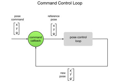
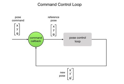
The command control loop is the outermost loop of our cascaded loop strategy. It’ll simply loop waiting for a command to be sent via a callback routine. The command will direct the robot to move to a new position and orientation, called a pose. For this we use a message type appropriately called “Pose”. The Pose message type is explained in the second post of this series. Once the command is received it will be sent to the pose control loop that is responsible for moving the robot to the new position and orientation. Once the new pose is obtained the program goes back to waiting for a command. The process is shown in the flow diagram below.
The callback function receives a message to move the robot to a new position and orientation. The robot’s current pose is added to the new reference pose. This is then used within the pose control loop to apply power to the motors and move the robot. A flag is set to tell the main loop that a command has been received. The ROSLOGx lines are home grown debug statements that print out to the ROS console. If anyone is interested in how these are implemented please let me know.
 //--------------------------------------------//
// Command callback
//--------------------------------------------//
void commandCb( const geometry_msgs::Pose& cmd) {

  // Print the new pose command message to the ROS console
  ROSLOGString("Received X, Y, Psi");
  ROSLOG3F(cmd.position.x, cmd.position.y, cmd.orientation.y);

  // Get the robot's current pose
  float *currentPose = robot->getLocalPose();

  // Print the robot's current pose to the ROS console
  robot->driveTrain.printLocalPose();

  // Assign new target pose. Current state + new pose.
  refPose[X_POS] = currentPose[X_POS] + cmd.position.x;
  refPose[Y_POS] = currentPose[Y_POS] + cmd.position.y;
  refPose[PSI] = currentPose[PSI] + cmd.orientation.y / (180/PI); // in radians

  // Print target pose to the ROS console
  ROSLOGString("Target Pose X, Y, Psi");
  ROSLOG3F(refPose[X_POS], refPose[Y_POS], refPose[PSI]);

  // Set the commandCalled flag
  commandCalled = true;
}
The main loop simply waits for a command to be received via the ROS subscribe protocol. The nh.spinOnce() statement polls the ROS server for new messages. Once the message is received and processed by the callback, the new reference pose is sent to the pose control loop.
//-------------------------------------------------//
// Main command loop
//-------------------------------------------------//
void loop() {

  // Loop until command is sent.
  if (commandCalled) {
    // Position control loop
    poseController(refPose);

    // Reset commandCalled flag
    commandCalled = false;
  }

  // Wait for subscribed messages
  if (nodeHandleCreated) {nh.spinOnce();}
  delay(1000);
}
Pose Control Loop
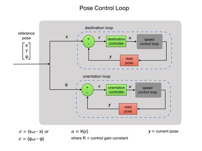
Once we have a command request to move the robot we need to implement a controller to guide it to the new destination and orientation. The controller is passed the reference pose that was computed in the command callback function. The reference pose becomes the new setpoint for the pose controller. The loop starts by calculating the difference between the robot’s current pose and its reference pose. The difference is referred to as the error. Given the pose error the controller will determine the speed setpoint for the wheels, which is then fed into the speed control loop. To complete the loop the new pose state is read from the robot and an updated error calculation is made. The loop continues until the pose error is driven to zero. There are separate loops for the destination and orientation control.
The first thing the poseController does is get the current pose from the robot. The current pose is obtained using a vector containing the X, Y positions and the ψ orientation, as shown in the above diagram. The current pose is subtracted from the reference pose using a function that subtracts two matrixes. The original linear and angular error values are saved since the pose error will constantly change as we process the move loops. We first process the linear move followed by the angular move. The fabs() function returns the absolute value of a float variable. For the angular move the control function takes in an arc radius around which the robot will turn. In this case, the arc length is zero requesting that we turn on the spot. There’s more detail on this later in the post.
 //--------------------------------------------//
// Control the position of the robot
//--------------------------------------------//
void poseController(float * refPose) {

  // Get the current x position of the robot
  float *currentPose = robot->driveTrain.getLocalPose();

  // Subtract the target pose from the current pose to get the error
  Matrix.Subtract(refPose, currentPose, 3, 1, poseError);

  ROSLOGFLabel("Start error X", poseError[X_POS]);
  ROSLOGFLabel("Start error Psi", poseError[PSI]);

  // Save the original pose errors
  float linear_error = poseError[X_POS];
  float angular_error = poseError[PSI];

  // -------- Process linear error ------------------
  if (fabs(linear_error) > 0.0) {
    moveLinear();
  }

  // -------- Process angular error -----------------
  if (fabs(angular_error) > 0.0) {
    // Pass in the arc length
    moveAngular(0.0); // Turn on the spot
  }
}
Linear Move
The code to move the robot in a straight line towards the reference destination is shown below. We first save the direction sign, positive for forward direction and negative for backwards. This will be used within the control loop to determine if we’ve overshot our target position. We set our wheel to the maximum speed and initialize a loop counter. The loop counter is used to implement a timeout. This is especially useful during testing so as you’re not running after the robot if the code is incorrect. Initializing the wheel to maximum speed does result in a jolt at the beginning of the move. This is mitigated somewhat in the speed control loop where it takes several time periods to reach the maximum PWM value. However, I do intend to implement a smoother startup transition at a later point.
We’re now ready to enter the control loop that continues until the X position error is driven to zero. The loop is processed every 50 milliseconds and is timed out after 5 seconds for testing purposes. If the sign of the pose error changes then we have gone passed our target position and we immediately break the loop and stop the motors. We want to slow down as we reach the target position so I’ve setup a couple of constants that start to reduce the motor speeds as we get to within 15% of the reference position. The Ki value ensures that we maintain a minimum speed at all times. These values can be tuned experimentally. The calculation will result in the maximum speed exceeding 1.0 during most of the run so we account for this condition in the code.
The new left and right wheel speed values are sent to the motors, and we go on to read the new pose value from the robot. The new error is calculated and we return to the top of the control loop. The loop is exited when the error is driven to zero and the command to stop the motors is sent.
 // PI control for pose loop. Adjust gain constants as necessary
const float Kp = 1.5; // Gets within 15% of target
const float Ki = 0.3; // Maintains a minimum speed of 0.3
//----------------------------------------------//
// Move in a straight line forward or backward
//----------------------------------------------//
void moveLinear() {

  // Save the direction of motion
  int dir = sgn(int(poseError[X_POS] * 1000));

  // Set min and max speed.
  float maxSpeed = 1.0;
  float wheelSpeed = maxSpeed;
  int loopCounter = 0; // Loop counter for timeout

  while (fabs(poseError[X_POS]) > 0.0) {

    // Process the loop every 50 milliseconds
    current_time = nh.now().toSec();
    while(nh.now().toSec() < current_time + poseLoopPeriod) {
        //wait 50ms
    }

    // Timeout after 5 seconds
    if (loopCounter > timeOut) { ROSLOGString("Timed out!"); break; }

    // End loop if the direction sign has changed (went passed the target)
    if ( sgn( int(poseError[X_POS] * 1000) ) != dir ) { break; }

    // Actuate the wheels

    // Slows down when we get near the target position
    // Sets wheel speed proportionally to the position error
    wheelSpeed = (poseError[X_POS] * Kp) + (Ki * dir); // Kp = 2.0, Ki = 0.3

    // Keep max speed to 1.0
    if (fabs(wheelSpeed) > maxSpeed) {
      wheelSpeed = (maxSpeed * dir); // Max 1.0
    }
    ROSLOGFLabel("wheelSpeed", wheelSpeed);

    robot->setWheelSpeeds(wheelSpeed, wheelSpeed); // left and right wheel

    // Get the current x position of the robot
    float *currentPose = robot->getLocalPose();

    // Calculate the error
    Matrix.Subtract(refPose, currentPose, 3, 1, poseError);

    publishToROS(currentPose);  // Publish robot state to ROS

    loopCounter++;

  } // End while loop

  // Stop the wheels
  robot->setWheelSpeeds(0.0, 0.0);  // Stop
  ROSLOGString("--- Done linear movement ---");
}
Note that since the robot is referenced in the local frame the move along the linear X position always sends the robot straight ahead regardless of where it’s initially pointing. There’s no global X position within a space that we’re trying to get to. I’ve tried to illustrate this in the following diagram. In the next series of posts I’m going to place the robot within a global frame in preparation for mapping and localization.
Angular Move
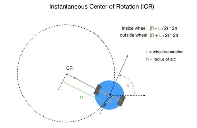
Before looking at the control loop that implements a change in orientation we need to define a point around which the robot’s wheels can rotate. This point is called the instantaneous center of rotation (ICR) and defines a point around which both wheels follow a circular motion. To obtain an angular movement the inside wheel would need to spin slower than the outside wheel, which can be accomplished successfully with a differential drive robot. The following diagram shows the math involved.
The following function is a member of the DriveTrain class. It takes in an arc radius and returns the ratio between the inside and outside wheels. If you follow the calculation through you’ll find that an arc radius of zero will return a ratio of 1.0, resulting in the robot turning on the spot.
 // ----------------------------------------------------------------
// Calculate the ratio between the two wheels while driving in
// an arc. arcRadius is the Instantaneous Center of Rotation (ICR)
// ----------------------------------------------------------------
float DriveTrain::calculateArcWheelRatios(float arcRadius) {

  // Get the distance that each wheel has to travel
  float insideWheel = 2*PI * ( arcRadius - (wheelSeparation/2) );
  float outsideWheel = 2*PI * ( arcRadius + (wheelSeparation/2) );

  // Return the ratio between the two wheels
  return (insideWheel / outsideWheel);
}
The moveAngular() function follows a similar pattern to the moveLinear() function. Since our wheels need to move at different speeds the ratio between the left and right wheel is obtained from the calculateArcWheelRatios() function, explained above. The resulting ratio will be between 1.0 and 0.0 so it must therefore applied to the slower spinning inside wheel. For turns, I’ve set the maximum speed to 50%. We then enter the main orientation control loop.
The primary difference between the orientation and linear control loops is that the wheels are moving at different speeds. We first calculate the speed for the outside wheel and apply our ratio to get the inside wheel speed. Note that the ratio will be 1.0 for a turn on the spot and that one wheel will be moving forward while the other is going backwards. This will be the case whenever the arc radius is less than half the length of the wheel base. At some point we have to decide which wheel is the inside wheel. This depends of course on whether we’re turning left or right. The determination is made and sent to the robot to actuate its motors. The remainder of the process is the same as for the linear move.
//----------------------------------------------//
// Move in an arc clockwise or anti-clockwise
//----------------------------------------------//
void moveAngular(float arcRadius) {

  // Calculate the relative wheel speeds based on the
  // radius of the turn.
  float ratio = robot->calculateArcWheelRatios(arcRadius);

  // Save the direction of motion
  int dir = sgn(int(poseError[PSI] * 1000));

  // Use half of max speed for turn.
  float maxSpeed = 0.5;

  // Set initial wheel speeds
  float outsideWheelSpeed = maxSpeed;
  float insideWheelSpeed = maxSpeed * ratio;

  int loopCounter = 0; // Loop counter for timeout

  while (fabs(poseError[PSI]) > 0.0) {

    // Process the loop every 50 milliseconds
    current_time = nh.now().toSec();
    while(nh.now().toSec() < current_time + poseLoopPeriod) {
        //wait 50ms
    }

    // Timeout after 10 seconds
    if (loopCounter > (timeOut*2)) { ROSLOGString("Timed out!"); break; }

    // End while loop if the direction sign has changed (went passed the target)
    if (sgn( int(poseError[PSI] * 1000) ) != dir) { break; }

    // Slows down when we get near the target orientation
    // Sets the outside wheel speed proportionally to the orientation error
    float outsideWheelSpeed = (poseError[PSI] * Kp) + (Ki * dir); // Kp = 3.0, Ki = 0.3

    // Keep max speed to 1.0
    if (fabs(outsideWheelSpeed) > maxSpeed) {
      outsideWheelSpeed = maxSpeed; // Max 1.0
    }

    // Calculate the inside wheel speed. Ratio will be -1 for turn on the spot
    insideWheelSpeed = outsideWheelSpeed * ratio;
    ROSLOG2FLabel("Wheel speeds (left,right)", insideWheelSpeed, outsideWheelSpeed);

    // Actuate the wheels
    if (poseError[PSI] > 0.0) { // Moving anti-clockwise. Inside wheel is left
      robot->setWheelSpeeds(insideWheelSpeed, outsideWheelSpeed); // (left wheel, right wheel)
    }
    else { // Moving clockwise. Outside wheel is left
      robot->setWheelSpeeds(outsideWheelSpeed, insideWheelSpeed); // (left wheel, right wheel)
    }

    // Get the current x position of the robot
    float *currentPose = robot->getLocalPose();

    // Calculate the error
    Matrix.Subtract(refPose, currentPose, 3, 1, poseError);

    publishToROS(currentPose);  // Publish robot state to ROS

    loopCounter++;

  } // End while loop

  // Stop the wheels
  robot->setWheelSpeeds(0.0, 0.0);  // Stop
  ROSLOGString("--- Done angular movement ---");
}
This completes phase one of the project. Please let me know if this series of posts has been useful. If so, I’ll continue to write updates on the project as it progresses. In the next phase I’ll be working at controlling the robot within a global reference frame, such as a living room (external kinematics). I’d also like to try and use an MPU for dead reckoning to confirm the odometry results coming from the encoders.
Please let me know if this series of posts has been useful.
I enjoyed reading them. I've also book-marked the thread. When it comes time to program my two-wheeled robots I'll revisit this thread. I probably won't be using ROS, but even without ROS there are many mechanical concepts that would apply in any case. So I thank you for writing the article. It was very well written with very nice graphics and code. Also very nicely organized with topic heading and nicely spaced paragraphs. I've seen some people try to explain things with such sloppy writing practices that I've had to copy their text, put it into a word processor, and re-organize it myself just to be able to follow what they are doing in a meaningful manner. So you get the technical Pulitzer prize from me. ?
Nice Job!
Material befitting a professional publication to be sure.
DroneBot Workshop Robotics Engineer
James

