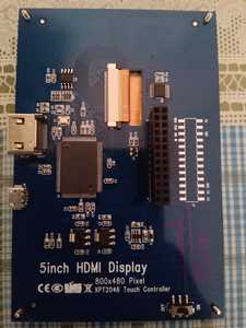
Hi. Today I've received my 5 inch HDMI display for Raspberry Pi.
But I see, that it's going to use up some of my GPIO pins on the Pi. Will I be able to work on physical computing and electronics, like blinking LEDs, using sensors, etc ?
Please help 🙂 🙏
I'm really worried about this stuff. 🥺
Will the LCD display work, if I power it through the USB cable and connect the HDMI port to the Pi and don't use the GPIO pins at all?
Why not just plug in the display, load an example sketch and try it ?
Anything seems possible when you don't know what you're talking about.
Hi @sumanta,
In case you are still puzzled.
The listing for what appears to be the same panel on Amazon includes:
Micro USB: get 5V power (not need when connect by GPIO)
GPIO (13*2): get 5V power& touch function
HDMI interface: for HDMI transmission
Backlight switch: turn on/off the backlight for saving power
That is:
the display 5V supply can come from either the group of 'GPIO pins', but only those pins connected to 5V or Ground, not an actual GPIO, or Micro USB socket ... either way no 'actual' GPIO pins are 'lost'
the display 'picture' comes from the HDMI connector ... no GPIO pins here
the touchscreen interface does use some GPIO pins .. so if you want the touchscreen to function, you will 'lose' some pins
Best wishes. ( NB I haven't got one .. this is assuming the Amazon listing is corrrect.)
Thank you so much for your advice. 😀
I was looking for something like this. So now, I will not have to use up 26 of the GPIO pins. I will use the 5V connecter that came with the display. Then I'll use the HDMI cable for displaying the screen on the display.
One more thing left. I'll have to search, which GPIO pins are used to provide the touch facility to the display. Only those GPIO pins will be used up then. That's the bare minimum which my display would need from the Pi GPIOs. 😉
The main problem which I was having, was that I couldn't access the VCC and GND pins on the Pi with the display on. But now, I think the problem is solved.
Thank you very much again. 😀 😀
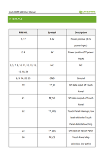
This is the user manual of the LCD display. According to this, I think I'll have to connect all the required GPIO pins to the display, except the 5V, 3.3V and GND pins, as I'll be powering up the display using the USB cable that came with the display. Am I right? 🙂
Hi @sumanta,
Out of curiosity I just watched part of a YouTube video on your type of touchscreen.
If I had one, I think my battle plan would be to connect it directly (as shown in the video) to start with using the short HDMI-HDMI linker, which I presume you have in your pack. Power it up, install all the drivers, etc. and make sure both the display and 'touch' functions work properly. I might even be tempted to make a backup of the SDcard and ensure it also works, as a 'golden' spare. This way, as you modify your system, you can check at appropriate stages to ensure it is still working in the knowledge that any problems are likely to be due the recent changes.
Then start to 'rearrange' the 'mechanics' of the connections between the boards, whilst maintaining the electrical conductivity, so that you 'regain' access to all the GPIO pins that display board covers up.
The two obvious approaches (I can think of .. I am sure there are others..) are either:
- completely separate the cards, and reconnect using flexible wires
- This method obviates the need for a 'tricky' soldering job, and enables you to minimise the number of GPIO pins dedicated to the touchscreen, but leaves you with two 'dangling cards' that will need some mechanical support for continued usage.
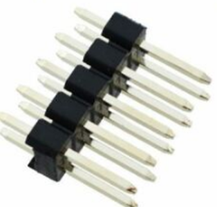
- Since the Pi 40-pin connector is 'through hole' 0.1" pitch, you might be able to solder a header of the 'general' style (40 pin version, of course) shown below to the underside of the Pi. You would then have a 'new' connector interface to attach your other sensors, etc. to.
-
- This method produces a more compact unit but needs some careful/tricky soldering.
- Also, the PCB picture you provided suggests 5 GPIO pins (+ ground) are 'used', but I suspect this is for 'flexibility' of different interfaces, and that the full functionality may be achieved with only some of these pins.
- To avoid problems, I would not recommend connecting a sensor to any GPIO pin (not including 5V and ground pins which can be multiply connected) that is connected to the display unit, even if the software interface in use does not make use of that pin. This might mean losing 2-3 more GPIO pins than absolutely necessary, but might make life easier in the future if you decide to change the display driver software, and the new software uses a different interface.
- The header I have shown would leave pins exposed. Corresponding sockets with 'long' legs could be similarly used if preferred.
- You must ensure the header has some mechanical support to ensure it cannot rip the pads off the Pi board.
- If you haven't used a soldering iron before, I would avoid this method until you have acquired some experience.
Just some suggestions. Good luck on your project! Dave
Hi @sumanta,
In reply to your recent query, my understanding (I haven't got one, so can't check, etc.) is that to get just the display to work, you need both of the following:
- +5V and ground (0V) ... for power. This can be either directly to the pins on the 28 pin connector, shown near the bottom of the connector in your photo, or by the microUSB socket. (You might be able to use 3.3V instead of 5V using different pins, but I doubt if that is helpful in your case .. I suspect that is for 3.3V processors, not the R Pi which is 5V.)
- HDMI diplay content, from R Pi.
To "add" the "touch" functionality, you also need to connect some of the pins near the top of the connector in your board photo. These are the pins labelled TP_xx in your most recent post. I haven't seen the software, but my initial impression is that there might be an opportunity to regain one or more of these pins, depending upon the interface standard chosen in the software. However, this labelling suggests that the expected interface is SPI, plus an interrupt, which will probably use all 5 pins, plus a 'local' ground, as shown in your photo.
Although all of the ground pins will be connected together, it is good practice to match by physical position, so the ground at the top of the connector for the touch interface, the one at the bottom for power.
I hope this is a little clearer.
Dave
completely separate the cards, and reconnect using flexible wires
- This method obviates the need for a 'tricky' soldering job, and enables you to minimise the number of GPIO pins dedicated to the touchscreen, but leaves you with two 'dangling cards' that will need some mechanical support for continued usage.
I think this method shall work for me, as I have never soldered anything.
+5V and ground (0V) ... for power. This can be either directly to the pins on the 28 pin connector, shown near the bottom of the connector in your photo, or by the microUSB socket. (You might be able to use 3.3V instead of 5V using different pins, but I doubt if that is helpful in your case .. I suspect that is for 3.3V processors, not the R Pi which is 5V.)
I want to use the micro USB socket for powering up the display, so that the 5v,3.3v and GND pins on the Pi are free for physical computing.
Anyways, thank you very much for your solutions. 😀
To "add" the "touch" functionality, you also need to connect some of the pins near the top of the connector in your board photo. These are the pins labelled TP_xx in your most recent post
@davee Then, I'll only need to connect 5 pins of the GPIO to the display.(The TP_xx ones)
5V, 3.3V and GND pins on the Pi shall remain free, as I'll power up the display using the USB cable.
This is my plan. What's your opinion on this? 🙂
P.S. What's the need of those pins labelled as NC in the datasheet?
Hi @sumanta,
You will also need to connect a ground to accompany the TP_XX wires... preferably use the nearest ground pin to the TP_XX wires on the connector.
And of course, you need the HDMI to HDMI link.
Otherwise, your plan concurs with my impression.
Good luck!
And of course, you need the HDMI to HDMI link.
@davee Forgot to mention the HDMI connector.
You will also need to connect a ground to accompany the TP_XX wires... preferably use the nearest ground pin to the TP_XX wires on the connector.
Only one ground connection will do, right? Because the display actually needs 5 GND connections.
Hi @sumanta,
Without seeing your physical wiring layout it is difficult to answer your query, but I suspect more than 1 ground return would be a better configuration.
It is difficult to explain why, but I'll try to give you an insight.
Electrical current always flows in a complete loop circuit.
Think of a simple circuit like a torch (flashlight) using an old style filament bulb.
When the torch is lit, the current flows from one terminal of the battery, through the bulb, through the (closed) switch, and returns to the second terminal of the battery.
If the circuit is interrupted at any point, such as by opening the switch, then current flow will cease.
In the case of the torch, the single circuit loop is obvious.
In the case of the R Pi and the touch display there are many such loops, but they all obey the same principle. The ground wires form part of those circuit loops, roughly corresponding to the return connection to the second terminal of the battery for the torch.
For complex circuits with many loops, the return currents may have an opportunity to interact with each other, which in severe cases may actually prevent the performing its expected function. Hence, it is common in digital circuits for signal wires to have accompanying ground return wires, so that the signals do not become 'mixed up'.
In the case of the R Pi and the touch display, having separate ground returns for the 5V supply and for the data (signal) wires labelled TP-xx seems a very reasonable approach.
If a single wire ground wire were used for both tasks, it is possible that high current pulses associated with the 5V power demands could be 'mistaken' for data signals on the the TP-xx lines.
Sorry, this is a very vague, yet rather long explanation.
However, poorly designed 'ground' return strategies are one of the most common reasons new circuit designs do not behave as expected. With digital circuits, it is most commonly seen as circuit that works 'most of the time' but occasionally fails ... sometimes described as due to a 'glitch'.
more than 1 ground return would be a better configuration.
@davee Okay then. I will surely follow your advice. 😀
But the problem is, I can allow only 4 GND connections for this purpose, as I'll be using this 5th one for physical computing. Will that be okay?


