After looking at a project where someone was using a 555 timer to measure the number of seconds a capacitor needed to discharge and thereby defining the capacity of the capacitor, I came up with the following idea.
The project on Instructables was merely to measure the number of seconds until the LED extinguished manually, so I thought that a µcontroller could be a better option and also replacing the 555 timer with an opamp.
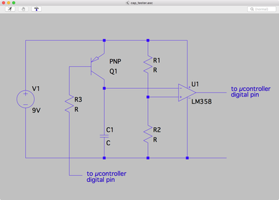
So I came up with the following schema.
The base of the PNP transistor Q1 is held high until the capacitor C1 is fully charged.
The digital pin is then set to LOW/OFF and the timer on the µcontroller starts.
When the voltage across C1 goes below the reference voltage R1/R2 the output of the opamp goes LOW/OFF the timer stops.
I know that R1, R2 and R3 need values, but I wanted to get some simple feedback on the basic idea.
C1 is the capacitor being tested.
Any comments or thoughts?
Keep It Simple Stupid (KISS) 😎

