
Notifications
Clear all
2022-01-31 11:10 pm
Here's a piece on analog multiplexors.
Edit: You could rig something up, methinks, whereby you turn "on" a given row and then use the mux to read each cell in the row, but just muxing rows and columns will give you the total effect of the row and the total effect of the column... which is where I got into thinking of clever checksum algorithms to know what the identity of the intersected cell was, but decided that was pretty convoluted.
I edit my posts to fix typos, correct grammar, or improve clarity. On-screen keyboards are evil.


2022-02-01 1:01 am
I was thinking about a bus architecture -- without yet knowing how this really works.
Don't worry about all that I can offer solutions on how to do that after you first figure out how you are going to identify the pieces.
All the previous suggestions should work, at a price and with varying complexity, but you were wanting a simple cost effective solution so that would mean simple physical contacts of some kind and maybe your suggestion of cheap resistors to identify the pieces.
I would also suggest it would require using an Arduino development board to test the code so add that to your cost.
The problem I see with magnets, to snap the pieces into position with the desired orientation, is the piece's magnets might interact with each other.
So you might be using chess pieces or scrabble tablets. Ideally you stick them to your "recognition" units.
The suggestion below is two metal washers of size such one fits inside the other so the orientation of the piece doesn't matter. A simple hole drilled in the board to fit a dowel fitted to the "recognition" units. Actually maybe a metal bolt instead of a dowel and that could be used as one contact thus only needing one washer.
to enlarge image right click image and choose open link in new window

2022-02-01 2:08 am
The suggestion below is two metal washers of size such one fits inside the other so the orientation of the piece doesn't matter. A simple hole drilled in the board to fit a dowel fitted to the "recognition" units. Actually maybe a metal bolt instead of a dowel and that could be used as one contact thus only needing one washer.
Nice thinking. You could have a pretty loose tolerance fit, so it's physically more like "placing the piece" rather that "slotting it into a hole."
I edit my posts to fix typos, correct grammar, or improve clarity. On-screen keyboards are evil.
Topic starter
2022-02-01 3:32 am
@binaryrhyme that's great -- had never heard of an analog multiplexer ... its surely a learning curve my jump into electronics ...
2022-02-01 3:35 am
... I'm a software guy myself, lol, so you and me both.
I edit my posts to fix typos, correct grammar, or improve clarity. On-screen keyboards are evil.
Topic starter
2022-02-01 3:43 am
@binaryrhyme I think, and hope, that me getting stuck all the time scratching my head while tinkering with my kids is as valuable a lesson as the electronics they are hopefully picking up.
Youtube is a great rescue as well, to review simple lessons and circuits presented again and again.
One great lesson, for example, was when both my kid and I realized that a transistor always has a small flow of electricity between the Base and Emitter -- so a led always was dimly on -- the inverter we built leaked ...
2022-02-01 3:53 am
@grossdan That's why you usually want the load on the non-combined current side of the transistor (the collector, aka the not-arrow pin.) The best learning is always found in the puzzling. 😉
I edit my posts to fix typos, correct grammar, or improve clarity. On-screen keyboards are evil.
Topic starter
2022-02-01 3:58 am
What was most puzzling initially, that the led was on when we completely disconnected the Collector from Vcc. We asked -- from where does the electricity come from -- until it dawned on us that there must always be a current between the base and emitter.
And, now i also grasped what you said -- that the load should be on the collector side, which is really switched on or off.
Biny reacted
2022-02-01 7:05 am
If you completely disconnected the collector from the Vcc then the base to emitter was acting like a diode.

A LED is also a diode (one way valve for the flow of electricity).
Essentially the current flowing between the base and emitter controls a much larger current flowing between the collector and the emitter. Thus we have an amplifier.
collector current = base current x beta
So if beta = 1000 then a 10 uAmp base current will result in 10000 uAmp collector current.
When you use it as a switch you are using it in the saturation and cutoff mode.

Biny reacted
Topic starter
2022-02-01 7:14 am
@robotbuilder thank you for the explanation ...
I wonder, how do inverters ICs cause zero current on their output pin, when the base is "off" i.e. in a low current state.
What additional circuitry do they add
2022-02-01 9:02 am
It has to do with the use of resistors that are used to limit the amount of current (amps) for any given force (volts).
You can imagine that a transistor acts like a switch in the circuit below. When the base current is high enough the collector to emitter will be closed and the collector will be connected to the ground. If the base current is OFF then collector to emitter will be open so full voltage ON will at the collector.
to enlarge image right click image and choose open link in new window

Biny reacted
2022-02-01 9:50 am
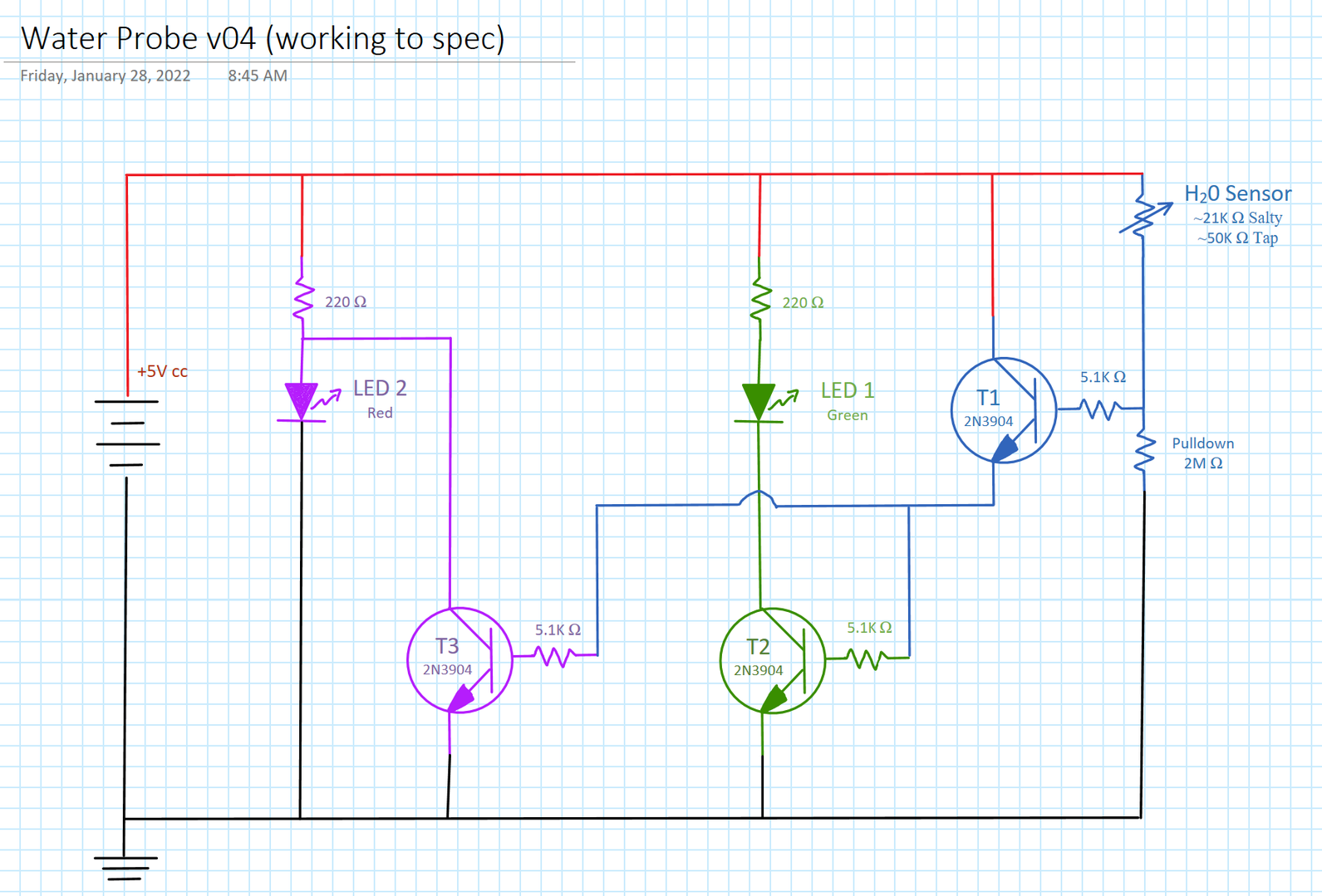
@grossdan To illustrate an inverter, in my most recent design of the water sensor (but there are several editions by other folks) T3 is a pretty classic inverter of T1, while T2 displays T1 directly, if that helps.
I edit my posts to fix typos, correct grammar, or improve clarity. On-screen keyboards are evil.
2022-02-01 12:10 pm
To elaborate on the circuit given by @binaryrhyme take the two extremes where we can imagine T2 and T3 to behave like switches. T1 and T2 will both be turned off or will both be turned on by T1.
If T2 is off then no electricity will flow through L1 while if T3 is off electricity will flow through L2.
If T2 is on then electricity will flow through L1 while if T3 is on electricity will not flow through L2.
The image below shows those two extreme states. In the in between states the transistors behave like variable resistors connected together. As the resistance between the collector and emitter is increased (in both at the same time by T1) the red LED will brighten while the green LED will darken. As the resistance is decreased (in both at the same time by T1) the red LED with darken while the green LED will brighten.
By the way I horizontally translated the circuit because I read them left to right (input to output).
to enlarge image right click image and choose open link in new window


2022-02-01 3:57 pm
@grossdan Check Lee Valley for magnets, some are small enough and the field can be to some degree localized by using the cups and washers.
First computer 1959. Retired from my own computer company 2004.
Hardware - Expert in 1401, and 360, fairly knowledge in PC plus numerous MPU's and MCU's
Major Languages - Machine language, 360 Macro Assembler, Intel Assembler, PL/I and PL1, Pascal, Basic, C plus numerous job control and scripting languages.
Sure you can learn to be a programmer, it will take the same amount of time for me to learn to be a Doctor.