@mrbond007 Doesn't your UPS have the abiity to notify you of a power event, I had that in the early 2000's at least.
First computer 1959. Retired from my own computer company 2004.
Hardware - Expert in 1401, and 360, fairly knowledge in PC plus numerous MPU's and MCU's
Major Languages - Machine language, 360 Macro Assembler, Intel Assembler, PL/I and PL1, Pascal, Basic, C plus numerous job control and scripting languages.
Sure you can learn to be a programmer, it will take the same amount of time for me to learn to be a Doctor.
Hi @mrbond007,
Just to clarify a couple of points, regarding my earlier post.
Background info
A common theme in the "Arduino world" is there are lots of variations of boards. Essentially there are a few 'lead' companies, of which Arduino itself is the most obvious. Arduino and other 'leads' publish their circuits and software with licences that enable other companies to create their own versions of Arduino boards. Some of these versions are close copies, whilst others have substantial variations --- and it is often difficult to spot the changes, until you find something doesn't work the way you expect.
In addition to the Arduinos themselves, other chips or modules, such as the Sim900A, which can be used for 'add-on' functions have a comparable world, with lots of copies and variants. However, many do not have a strong 'lead' company comparable to Arduino. The 'master' design is often based on an application note or demo board by the original chip/module company, but this is sometimes only a rough 'concept level' design which subsequently gets copied and altered with little traceability or documentation.
And to further complicate the situation, 'popular' chips and modules themselves often attract copies, some almost identical ... others not so close...
There are a few companies like Adafruit who do a generally do a good job of producing add-on boards with documentation, etc. but they are the exceptions.
So bearing this general background of variability in mind:
-----------------------------------------------------------------------------------------------
- Your reference to a GSM900A module may not be a precise reference to a single design, but to a number of variations on the same theme. There might only be a single SIM900A chip/module (e.g. see https://components101.com/sites/default/files/component_datasheet/SIM900A%20Datasheet.pdf), but the GSM900A modules incorporaing the SIM900A might differ. Hence, things like pin numbers/positions or provision of a voltage regulator might differ depending where your module came from. You need to carefully check the connections, voltages, etc. for the particular module you have.
- .
- The data sheet I found said that the voltage supply to the GSM900A module had to be in the range 3.3V to 4.5V. That implies, exceeding 4.5V, even for a microsecond, risks damaing it permanently. Obviously any real board is likely to tolerate a very small overvoltage. e.g. it might tolerate up to 5V, but I would not be sure. I can almost guarantee it will not survive 12V. An extra voltage regulator is called for!
- The GSM900A module article I saw mentioned some configuration pins on the GSM900A module that must be set to match either a 5V or 3.3V Arduino ... make sure you set these correctly.
- I haven't seen the current demand information on the GSM900A, though I would expect the peaks when transmitting could easily exceed 1 Amp. However, I would also expect these peaks to be very short in time, and to some extent supplied by the decoupling capacitors, so the average current should be much less. I did wonder if the little PP3 style battery shown in the reference you supplied would 'struggle' a little. Personally, I think I would have tried 6 x 1.5V AA cells in series to give 9V. This also suggests the regulator for the GSM900A supply should be able to cope with at least 2A peak current. This is an area that some prototyping tests aand measurements need to be done to determine the actual situation.
- A rechargeable battery and charger unit is a possibility, but is adding yet more complexity. I would get it working with simple alkaline batteries ... there can always be a Mark II later on! The trick is to get a simple project working first ... then develop it further if you wish.
- I haven't looked out the data connections between the Arduino and the GSM900A, but a pair of lines (plus common 0V line), is a common configuration. The GSM900A pins are probably predefined by the module design, but Arduinos have several similar pins that are configured in software. Hence, checking them involves ensuring the software matches the wiring choices.
- Note the wiring of the Tx and RX pins between the Arduino and the GSM is like two people having a chat ... each person has a Tx [transmitter] (voice output) which sends to the other person's Rx [receiver] (ears).
- Sorry, I can't follow your recent discussion above about J2 above. Accurate diagrams are a lot easier to follow!
-------
Overall, I recommend you post an updated schematic, showing all of the parts. You may find it easier to print out the Fritzing diagram, and use a pen to add in UPS, wall wart, etc. that are not on the breadboard. Then post a photo or scan. It might help post references to the actual GSM900A and UNO you have procured, although sadly some supplier details are very short on useful information.
Best wishes, Dave
@mrbond007 Are you having PCB's made? How many are in your project and is it for school or work?
Neither @zander. I'm doing this as I'm interested in Arduino and electronics but never got a chance till recently to learn or try my hands on it. I'm a Law student. I use my spare time to learn and play with Arduino.
@mrbond007 Doesn't your UPS have the abiity to notify you of a power event, I had that in the early 2000's at least.
Unfortunately, it does not have this function.
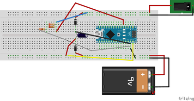
I apologise for the late reply. Unfortunately, I ran out of a few components, and the delivery of the components took a bit more time than usual. At the time of writing this post, the project stands complete and works as expected. Thanks for your help and time, @zander and @davee. I want to share details of the changes I made to the project. I powered the GSM module using a wall wart connected to a UPS(I did not use the 5V pin of the Arduino to power the GSM 900A module). Another wall wart which connected to a socket connected AC Mains. I have attached my code and circuit/breadboard diagram. To avoid a complex diagram I have not included the GSM module.
#include <SoftwareSerial.h>

// Configure software serial port
SoftwareSerial SIM900(7, 8);

//Variable to save incoming SMS characters
char incoming_char=0;
//Allarm status
byte alarmStatus = LOW;

void setup() {
  // Switch on the GSM shild
  pinMode(2,INPUT);
  // Arduino communicates with SIM900 GSM shield at a baud rate of 19200
  SIM900.begin(19200);
  // Give time to GSM shield to log on to network
  delay(30000);
  // AT command to set SIM900 to SMS mode
  SIM900.print("AT+CMGF=1\r");
  delay(100);
  gsmModuleReady();
  // Set module to send SMS data to serial out upon receipt
  // SIM900.print("AT+CNMI=2,2,0,0,0\r");
  // delay(100);

}

void loop()
{
  // Display any text that the GSM shield sends out on the serial monitor
  if(SIM900.available() >0) {
    //Get the character from the cellular serial port
    incoming_char=SIM900.read();
    //Print the incoming character to the terminal
    Serial.print(incoming_char);
  }
  while (digitalRead(2) == HIGH) {}
  if(digitalRead(2) == LOW && alarmStatus == LOW) {
    // whait 1" more and send message if pin 2 is already LOW
    delay(1000);
    if(digitalRead(2) == LOW) powerDownAlarm();
  }
  while (digitalRead(2) == LOW) {}
  if(digitalRead(2) == HIGH && alarmStatus == HIGH) powerRestored();
}

void powerDownAlarm()
{
  // Set recipient's mobile number in international format
  SIM900.println("AT + CMGS = \"+xxxxxxxxxxxxx\"");
  SIM900.println("AT + CMGS = \"+xxxxxxxxxxxxx\"");
  delay(100);
  // Set SMS message
  SIM900.println("*** AC Mains Down ***");
  delay(100);
  // End AT command with a ^Z, ASCII code 26
  SIM900.println((char)26);
  delay(100);
  SIM900.println();
  // Give module time to send SMS
  delay(5000);
  alarmStatus = HIGH;
}

void powerRestored()
{
  // Set recipient's mobile number in international format
  SIM900.println("AT + CMGS = \"+xxxxxxxxxxxxx\"");
  SIM900.println("AT + CMGS = \"+xxxxxxxxxxxxx\"");
  delay(100);
  // Set SMS message
  SIM900.println("*** AC Mains Restored ***");
  delay(100);
  // End AT command with a ^Z, ASCII code 26
  SIM900.println((char)26);
  delay(100);
  SIM900.println();
  // Give module time to send SMS
  delay(5000);
  alarmStatus = LOW;
}

void gsmModuleReady()
{
  // Set recipient's mobile number in international format
  SIM900.println("AT + CMGS = \"+xxxxxxxxxxxxx\"");
  SIM900.println("AT + CMGS = \"+xxxxxxxxxxxxx\"");
  delay(100);
  // Set SMS message
  SIM900.println("*** GSM Module registered on network ***");
  delay(100);
  // End AT command with a ^Z, ASCII code 26
  SIM900.println((char)26);
  delay(100);
  SIM900.println();
  // Give module time to send SMS
  delay(5000);
}
Hi @mrbond007,
Thanks for responding in that kind manner .. I hope your system proves to be a useful asset and rewards you for your time and effort.
Perhaps others watching this forum will find your solution interesting and helpful.
Best wishes, Dave
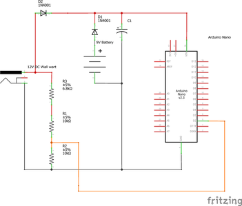
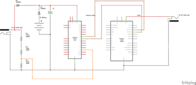
Thank you @davee. I'm attaching two schematics. Can you please take a look? Is something missing or wrong?
Without GSM Module
With GSM Module
I have one query. Will the GND of GSM Module go to GND of Arduino?
Hi @mrbond007,
Sorry, I am writing these comments in the hope they may be helpful, but I have not used the GSM module, and I am relying on a quick look at schematics, etc. that I have found on the web, which means there is a substantial risk I have missed or misunderstood something. (I accept no liability for errors, omissions, etc.)
----------
Re: Will the GND of GSM Module go to GND of Arduino?
Yes. I think your wiring diagram shows this connection of grounds, from the GND pin on the Nano module to the AGND pin on the GSM module. This connection is required.
Note it is important to avoid a 'ground loop'. If the 0V line of the two "5V" power supplies to the board are also connected together, such as will happen if both power supply outputs connect to the 'mains' earth supply, then this could result in unexpected electrical noise problems. This is unlikely to be problem with most wall warts. A simple check is to look for the absence of a mains earth pin on at least one of them. This would be obviously true if it has only two pins on the mains side, or if the third pin is totally made of plastic.
-------------
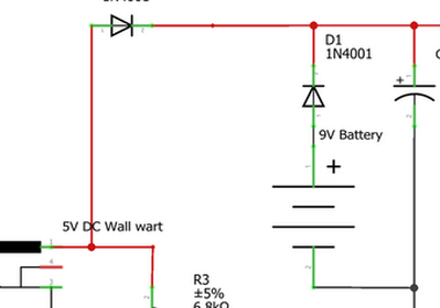
This snip shows this power supply to be 5V, instead of 12V. Some 'flexibility' on the voltage of this supply is feasible, but it must be more than battery voltage to ensure that it powers the Nano in preference to battery.
Also, the potential divider made of R1, R2 and R3, assume a voltage of about 12V.
So this power supply needs to be in the range 10V to 12V output ... or other circuit changes will be needed to compensate.
------
I hope this helpful. Best wishes, Dave


