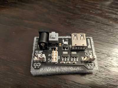
I've got an Elego MB‐V2 breadboard power supply, similar to this https://www.docdroid.net/9oyf/mb-v2-datasheet-pdf . It's connected to some kind of unknown Chinese brand of 9V DC wall charger (I forget the name that people seem to use for these).
When configured for 3.3V, it's providing about 3.32V and that seems to work ok. When configured for 5V, I'm only measuring 4.96V.
Which is the likely culprit for the drop in voltage at 5V, the breadboard power supply or the 9V DC wall charger? Should I just buy a new breadboard power supply?
The one I have is a bit different to most online. Mine looks like this:
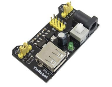
Which doesn't look the one advertised in the kit I bought:  .
.
Thanks
I tried another wall adaptor, set it to 6V and I got exactly the same 4.96V.
Interestingly, this adaptor has swappable barrels, so I took the barrel off and measured across the two pins. It's a 9V adaptor and I measured 8.91V.
I assume this makes sense to someone here!
You made me look! I have 2 breadboard power supplies (bought at the same time). I went and checked and sure enough, one of them was not giving me 5v! So I checked them both, with 2 multimeters (Unit-T & Equus).
Power supply 1: Uni-T 9.11v (in); 4.98v & 3.346 out || Equuis 9.11v (in); 4.98v & 3.34v
Power supply 2: Uni-T 9.11v (in); 8.34v & 3.294v || Equuis 9.12v (in); 8.35v & 3.29v
I was using a 9v 700mA wall wart for both. Looks like I have a problem - glad I did not plug anything onto those rails on the breadboard!
This is the breadboard power supply I have two one of:
https://components101.com/sites/default/files/component_datasheet/MB102-Datasheet.pdf
"Hardware eventually fails. Software eventually works." - Michael Hartung
What! Those numbers on the 5V rails are crazy. Maybe we should throw them away.
I'll test tomorrow with USB plugged in rather than barrel jack, but yes....I was going to clip the leads and use only the other rail (backup)
"Hardware eventually fails. Software eventually works." - Michael Hartung
Multimeters are not that precise. 4.96v is probably close enough, or at least within spec. I really wouldn't worry about it. For Arduino and Arduino kits, that sounds about right. If you really want that kind of precision, there are gear that you can buy. Sounds like overkill to me though. You can't expect a Ferrari for the price of a Kia.
That's what the last band on a resistor is for. To tell you how close of value to the stated rating it will be. I wouldn't expect all the resistors in the band to be exactly the same ohms. They would vary. The same would be true for any component. They make better ones but unless you are working in a specific field that would need the quality component, the cheap ones will work fine. So as long as you aren't creating any medical devices with your Arduinos(and you shouldn't be), it will be fine.
I was trying to use the breadboard PS to power a sensor that needed 5V but it didn't work. That caused me to pull out my multimeter. Perhaps I'll try the PS and sensor again to make sure I didn't screw something else up.
I have found those power supplies to be a load of crap for the most part. I got a group of 5, as they were near the same price as one when shipping was added. Not one of them delivered proper voltage, though they were in tolerance. (such as the one above in this discussion.) However, they could supply only a small fraction of the current they were supposed to deliver without dropping out altogether.
My solution;
I set up a series of 78xx linear voltage regulators, and one LD1117v33 to make a power supply of my own. Nothing to write home about, but cheap and easy. The regulators are 12v, 9v, 5v, and 3.3v. I used the schematic in the data sheet and set them up in series so that none of the individual regulators have to dissipate a bunch of heat if a load near it's current rating is applied. I have them fused at 1A, so there is only 1A available for the entire supply all voltages combined. It has covered all of my needs thus far.
Each voltage has a set of headers for 5 outputs each, I've never used more than two of a given voltage at any time at this point. Grounds are all common. I found a wall wart that put out a bit over 13.5 volts at around an amp and a half. It provides enough headroom for the first regulator of 12v.
I intend on taking it a bit further with a center tapped transformer and set up the negative rail to match the positive rail for working with op-amps. Just don't have the cash for that as yet.
I could work up a schematic if anyone is interested.
I was trying to use the breadboard PS to power a sensor that needed 5V but it didn't work. That caused me to pull out my multimeter. Perhaps I'll try the PS and sensor again to make sure I didn't screw something else up.
I bet if you looked at the datasheet for the sensor, that your supplied voltage is probably above the minimum voltage for the sensor, assuming its listed.
If the supply was not providing enough amperage, I would expect it to drop in voltage. So that begs the question, was that the voltage under load? I would still call it within spec if it was. Although, I would expect it to drop down much further if it couldn't keep up with the current.
I'll double check this when I can, thanks.
@centari, I'd be interested in seeing your schematic, though it's a bit more than I need. I only need 3.3V and 5V.
It was my understanding that all of these components would not work to the exact specs. Yesterday, I did the experiment from Chapter 8 of the new Raspberry Pi Pico Getting Started book and it stated that when using a potentiometer to measure voltage:
All electronic components are built with a tolerance, which means any claimed value isn’t going to be precise. In the case of the potentiometer, it will likely never reach exactly 0 or 100 percent of its input – but it will get you very close!
It seems to me that if the 5v breadboard power supply gives you an output of 4.96v, then it's working as it should. If you need at least 5 volts then wouldn't you use a voltage regulator or something else that would provide more than 5 volts?
Cheers!
--->Sean
(◕(' 人 ') ◕)
Power supply 1: Uni-T 9.11v (in); 4.98v & 3.346 out || Equuis 9.11v (in); 4.98v & 3.34v
Power supply 2: Uni-T 9.11v (in); 8.34v & 3.294v || Equuis 9.12v (in); 8.35v & 3.29v
Yes, that second 5-volt output is definitely a cause for concern! Out of curiosity did, you have a load on the outputs when you tested them?
What! Those numbers on the 5V rails are crazy. Maybe we should throw them away.
Yikes - I bought a sheet (yes, they come in sheets) of 10 of those a few years back, and I really don't want to throw them all away!
As for the original post, 4.96-volts is perfectly fine for a 5-volt logic device. In fact, the TTL specifications allow the supply voltage to range between 4.75 and 5.25 volts safely. These modules use inexpensive 3-pin linear regulators, and they can sometimes be off by a small bit. I suspect the board @theoutlander was testing has a bad 5-volt regulator.
😎
Bill
"Never trust a computer you can’t throw out a window." — Steve Wozniak
Power supply 1: Uni-T 9.11v (in); 4.98v & 3.346 out || Equuis 9.11v (in); 4.98v & 3.34v
Power supply 2: Uni-T 9.11v (in); 8.34v & 3.294v || Equuis 9.12v (in); 8.35v & 3.29v
Yes, that second 5-volt output is definitely a cause for concern! Out of curiosity did, you have a load on the outputs when you tested them?
@dronebot-workshop Not in the above, but I did check with a fan running on what I thought was the 5v output. I'll rerun tests with a load tonight.
"Hardware eventually fails. Software eventually works." - Michael Hartung
I didn't have a load on the circuit during my measurements. When I got the 8.91V reading, I wonder if I didn't re-seat the jumper (3.3V/5V) properly and it was wide open to the 9V input voltage from the wall adaptor.


