The power supply article is just beautiful and I am going to build one . I just need to know what king of fuses and the amperage. He says he uses 3 of them . I wish to do so since I have ruined projects before due to lack of them.
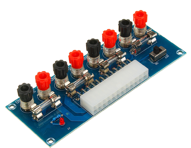
I found this item and bought it to make the job easier. I haven't received it yet so I can't recommend it yet. Buy at your own risk.
Or you can just search for XH-M229 on ebay.com for a number of sellers.
@ruplicator Did you ever set this up? Any update as far as a review and ease of use?
Robert T.
IT Systems Administrator
"In the storms of your life may your heart soar like the eagle." ~ Unknown Author
He says he uses 3 of them .
I assume by "he" you mean me lol?
In a perfect world, the amperage rating of the fuses should match the output rating of the power supply. But it's more likely that you'll need to use the nearest value to the rating instead.
The reason I don't specify the fuse values is that different ATX power supply have different current ratings. My supply was a surplus one from an old Windows XP machine, and I used the following values:
- 3.3v - 20A
- 5v - 30A
- 12v - 10A
But again, these values worked for my power supply. Look on the label for your supply and choose fast-acting 250-volt fuses that are rated just a bit below the maximum ratings.
And also mote that many cheaper power supply could never possibly sustain the maximum outputs they claim! So you might want to be conservative and fuse them with even lower values.
😎
Bill
"Never trust a computer you can’t throw out a window." — Steve Wozniak
@roborobs Unfortunately, it got lost in the mail and I got a refund. It took so long to get it resolved that I 3D printed a front plate that fit the power supply. The unit I ended up with works fine but I didn't get to try out the one I posted.
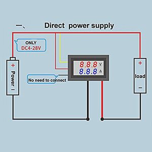
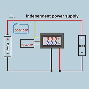
I just read through the tutorial. The panel meter is a nice addition. I searched for the part and found many Amazon sellers. The product literature shows two connections; direct power supply, and independent power supply.
We should use the direct power supply configuration?
ZoolanderMicro, where small ideas are a big deal
I have an ATX power supply breakout board similar to the one Ruplicator ordered. I use it mainly to switch the power supply on and off. I tap the accessory wires by attaching fan header to Molex adaptors, and then using F to M jumpers from the pins of the fan headers to the breadboards. Kind of messy as you can imagine. This could really help to neaten up my bench. Some of my circuit boards are designed to work from 9v power supplies. I add an onboard 5v regulator to supply power to a micro-controller, and use 9v to run LEDs. I think I will add a 9v regulator to this project. If I'm only reading voltage and current from the patched in supply line, I could add a rotary switch as a voltage selector instead of using a patch wire. It's getting pretty fancy now! I have 3mm (1/8") birch plywood that will make a nice panel face. This sounds like another great project 😉
ZoolanderMicro, where small ideas are a big deal
For the voltages coming out of an ATX supply, either direct or independent is fine... but with a repurposed ATX supply "wires giving you 5 or 12 volts" is something you have tons of, so it's pretty easy to run in independent mode as well.
"A resistor makes a lightbulb and a capacitor makes an explosion when connected wrong"
"There are two types of electrical engineers, those intentionally making antennas and those accidentally doing so."
The key difference between "direct" and "independent" is that the direct uses the single power supply to power both meter and load.
In the independent supply the load requires a 100v supply and this is much too high for the meter so a separate supply must be used for it.
I am having a hard time determining the right rotary switch to use. I would like to select between 3.3v, 5v, 9v (using a T7809 regulator), 12v, and AUX (2.1mm DC jack). I cannot find a 1pole/5Position rotary switch. I suppose a 2pole/5pos switch will work. I cannot find decent pictures or descriptions to clarify the difference. I am also assuming that the Make Before Break (MBB) is the correct type to use. I'm guessing that there is a break in the circuit between the rotary detents. Jameco has a 2pole/6pos (2235778) and the recommended knob (2235778) a classic pointer type (nice).
ZoolanderMicro, where small ideas are a big deal
@zoolandermicro Ive got about 5 of these in use, the 0-100 voltage is the supply power going into the meter from your supply, the 4-30 supplies power to run the number leds (readouts), I used the 5V standby supply (purple wire of the computer power supply) for the 4-30V on my units.
I would go with the 6/2 switch. You can double up on the contacts per volt line to handle the amps and by having 6 position you can use the empty one for an "off" position.
I would go with the 6/2 switch. You can double up on the contacts per volt line to handle the amps and by having 6 position you can use the empty one for an "off" position.
Thanks BunnyKiller, I just ordered the 2pol/6pos rotary switch. This will be for switching the supply output parallel to the meter. I will also have terminal posts for the various voltages that won't be monitored by the meter. I ordered test leads with banana plugs and mini-grabber ends. It will be easy to grab onto pin headers inserted into the breadboard. I have a box of old power supplies. How can you tell if a load/power resistor is necessary?
ZoolanderMicro, where small ideas are a big deal
Being the newbie here I am posting my1st post.
I am converting and old Dell computer PSU (Thermaltake TR2-430) into a bench supply based upon the YT video and DB tutorial. The power supply is a 24 pin version. I have copied the schematics of that plug and have some questions.
First there is a small diameter brown wire that is crammed into the #13 pin along with orange wire. What is this brown for?
Also, as a newbie, I do not understand -12v wire. What is it used for?
I have snipped off all the "extra" wiring harnesses.
As info I am making power supply for powering up details on an N scale model RR.
Thanks in advance,
Carl


