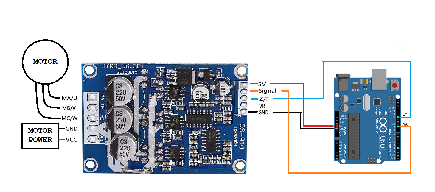
I guess it is difficult to explain clearly without seeing the project in front of you...
So provide the connections. I have found your statements very confusing.
I can already get the motor to spin anticlockwise using the following methods:
a) by switching any 2 wires'
b) by using a pot on its own,
c) by using a combination of the pot and the Arduino
what I can't seem to do is to get it to change rotation by using the Arduino and the brushless controller in my original post.
c) by using a combination of the pot and the Arduino
But using the pot and the Arduino is using the Arduino. You can replace the POT input with just code. Or is there something I am missing here?
Have you made two connections from the Arduino to the controller?
One Arduino pin output to provide PWM value and another Arduino pin output to switch direction with a HIGH or LOW value?
Show the code and the circuit.
Here is a robot using brushless motors. https://www.parallax.com/propeller-2-brushless-dc-motor-controller-system-update-use-hoverboard-motors-on-your-next-robot/
Here is the sort of information that might help others help you.
To enlarge image, right click image and choose Open link in new window
Most strange. When I tried to Open link in new window with the image all it did was download the image. It was a rush to add edits before the 1 hour limit was up.
It may be because I accidently attached a .bmp instead of a .png or jpg version.
It is just an illustration of the kind of information that anyone offering suggestions might need it is not meant to be a solution.
@will , I think I have tried that but I'll another go...
The wiring diagram in post https://forum.dronebotworkshop.com/postid/33680/ clearly shows that Z/F is NOT connected to a PWM pin and indicates a value which is either HIGH or LOW.
Anything seems possible when you don't know what you're talking about.
That was not a solution only pointing out that without a complete understanding of what @spikemjv had done and details like the connections tried and so on it is hard to give any useful suggestions.
The source of the above connections came from this article,
@robotbuilder FYI @will But of interest is that the normal digital pin capable of High/Low is called DIRECTION on the SOLO board exactly as Will pointed out. That still works without te SOLO board.
First computer 1959. Retired from my own computer company 2004.
Hardware - Expert in 1401, and 360, fairly knowledge in PC plus numerous MPU's and MCU's
Major Languages - Machine language, 360 Macro Assembler, Intel Assembler, PL/I and PL1, Pascal, Basic, C plus numerous job control and scripting languages.
Sure you can learn to be a programmer, it will take the same amount of time for me to learn to be a Doctor.
@robotbuilder FYI @zander FYI @spikemjv
Just from basic principles, why would you need a PWM signal to indicate forward or reverse ? Why pass a pulsing value to indicate a boolean choice ?
Anything seems possible when you don't know what you're talking about.
@will @robotbuilder @spikemjv It's hard to fool Will!
First computer 1959. Retired from my own computer company 2004.
Hardware - Expert in 1401, and 360, fairly knowledge in PC plus numerous MPU's and MCU's
Major Languages - Machine language, 360 Macro Assembler, Intel Assembler, PL/I and PL1, Pascal, Basic, C plus numerous job control and scripting languages.
Sure you can learn to be a programmer, it will take the same amount of time for me to learn to be a Doctor.
I noticed the controller being used by @spikemjv has a VR input (Variable Reluctance) wheel speed sensor so the motors most likely have such a sensor.
https://www.ncbi.nlm.nih.gov/pmc/articles/PMC3231115/
Just as way back in my early interest in teaching myself basic electronics I found different books provided information or a clear explanations not all found in one particular book. So the more sources you learn from the more likely you will get to know how everything works. IMHO
This thread has been a learning experience as I read about these brushless motors.
@robotbuilder @will @spikemjv Very interesting stuff for me as the last motor theory I ever studied was about 1962. I of course have heard of brushless and know my best power tools use them but that's about the limit of my knowledge.
First computer 1959. Retired from my own computer company 2004.
Hardware - Expert in 1401, and 360, fairly knowledge in PC plus numerous MPU's and MCU's
Major Languages - Machine language, 360 Macro Assembler, Intel Assembler, PL/I and PL1, Pascal, Basic, C plus numerous job control and scripting languages.
Sure you can learn to be a programmer, it will take the same amount of time for me to learn to be a Doctor.
Thank you both robotBuilder and Will for your contributions. As I have admitted in my introduction, my knowledge of electronics is very limited and I have join the forum to learn from kind members like yourselves. However, I think both of you may have guided me onto the path to finding a solution. I think I have been connecting the Z/F connection from the controller board to the wrong pin (PWM) on the Arduino (a little knowledge could be a dangerous thing 😀 ).
The diagram that you both have referred to in your previous posts provides a very good illustration of where the connection from the Z/F pin should be placed (one of the ANALOG pins, right?).
The rest of my connections between the Arduino, Motor and Controller Board are the same as indicated in the diagram provided by yourselves.
I will have a go at making the change later and I will let you know how I get on.
Once again thank you both for your patience and help.
Spike
Correction to my last message the : The Z/F is NOT connected to a an Analog pin but to a standard IO pin on the Arduino (in the example pin 12).
Correct.
// global space define ZF as 12
int const ZF = 12;
// int the setup
void setup(){
pinMode(ZF,OUTPUT); // same as pinMode(12,OUTPUT); set pin to output
// in the loop
void loop(){
digitalWrite(ZF,HIGH); // same as digitalWrite(12,HIGH); Set to 5v
digitalWrite(ZF,LOW); // same as digitalWrite(12,LOW); Set to gnd
Do the motors have wires for a VR pin?
If so it might be important for proper operation and control.
Thank you both for all your fantastic help. I changed the connection for the Z/F pin to a normal OUTPUT pin. I also found that I had to use the VR pin on the controller and everything works fine. The only difference from the diagram you provided is, (in the diagram VR is not used)
my final connections are:
Signal pin on controller to (PWM) Pin 9 on Arduino
Z/F. pin on controller to IO Pin 12 on Arduino.
VR pin on controller to IO Pin 8 on Arduino
You guys have been a great help ....
I got about 6 part complete WORX robotic lawnmowers as a bundle from ebay , - no mainboards, but all are driven by brushless DC (BLDC) motors of the same type, (the cutter blades are also driven by BLDCs) if I can get them working using the Arduino and suitable controller boards then that would be good.
Going to sort out bump sensors for the Landroids next - should be straight forward...
Thanks again
Oh! I forgot to say thank you to Ron as well for his inputs into finding a solution to my question... still getting use to navigating the platform...


