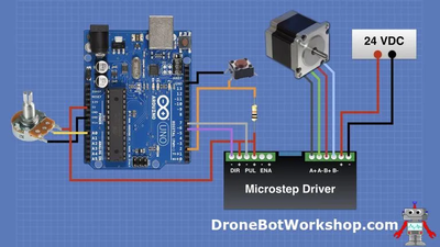
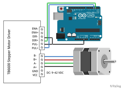
I am following https://dronebotworkshop.com/big-stepper-motors/ .
The motor locks up but does not move.
Ralph
Which part of your setup doesn't exactly match Bill's setup ?
Anything seems possible when you don't know what you're talking about.
I am using a different Microstep Driver.
I am able to use the driver and stepper motor with different code.
Apparently from searching the old post I was able to get this to work, at least in part.
Ralph
I am using a different Microstep Driver.
I am able to use the driver and stepper motor with different code.
That suggests that the problem is in the difference in the code or in the settings of the microswitches. Perhaps you're trying to drive the stepper too quickly, that can result in it locking up.
Anything seems possible when you don't know what you're talking about.
I had other code that that locked up the stepper and it was growling/vibrating.
The motor will click once and then is just dead with a locked up shaft (I cannot turn the
shaft). I fixed the other code by slowing down the motor which I will try, thank you.
Ralph
Thanks for the help.
I have the motor turning very very very slooowly!
I connected a common (Arduino GND) to the High voltage motor leads.
Should the switch for direction be a momentary contact switch?
Ralph
I connected a common (Arduino GND) to the High voltage motor leads.
That sounds horribly wrong. Can you please post your wiring diagram (and indicate the last connection you mentioned) ?
Anything seems possible when you don't know what you're talking about.
My wiring is as what was illustrated in the web post, https://dronebotworkshop.com/big-stepper-motors/
With the addition of the Common ground.
Ralph
Do you mean that you connected the 24V GND to the Arduino GND ?
I think it should be a momentary switch for reverse.
Anything seems possible when you don't know what you're talking about.
Yes, Arduino GRN to 24V GRN, a "Common" ground.
The motor turns very slowly, the pot makes no difference.
The direction switch does nothing also.
Ralph
I'm not sure why there's no common ground shown on the Fritzing diagram, seems like it should be there to force both voltages to the same base.
Not sure why it doesn't work except that you're not using the same driver as Bill.
Anything seems possible when you don't know what you're talking about.
Hi @ralphxyz,
I have never used this kit, but a quick look on the web for a manual at
https://www.makerguides.com/wp-content/uploads/2019/10/TB6600-Manual.pdf
showed similar wiring to Bill (common anode) , and confirmed use of optoisolators in the text, but did not provide a circuit explanation.
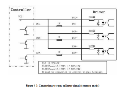
A web search for MA860 yielded a manual which clarifies the approach (for the MA860) and is probably relevent to your controller as well.
https://manualzz.com/doc/7184361/user-manual-of-ma860h-n
where the controller on the left would be your Arduino with common anode supply, in agreement with Bill's diagram. Each of the three drive signals power an LED inside an opto coupler inside the drive unit, as shown on the right hand side of the diagram. (For 5V Arduino, the external resistors marked R are "0 Ohm", i.e. just wire links)
There is no need for a common earth between the Arduino and the motor controller ... and, whilst it might be harmless in many cases, to avoid problems, I strongly recommend you do not common the earth between the Arduino and the controller.
i.e. Bill's diagram is complete, assuming the Arduino is powered by either the PC USB link or through the barrel connector by a separate supply.
The action of the switch and the pot would depend upon the Arduino software ...
I didn't read the makerguide I referenced above properly, but I did spot some cautions about some suppliers using different (fake) chips ... you might like to check it doesn't apply in your case.
Good luck, Dave
The only way the motor works is with a common ground!
The motor turns very slowly it only gives a slight click without the common ground.
Will, I just copied the image from Bill's page so of course there is no common wire shown.
The code from one of the Makerguides TB6600 Tutorials works, the motor runs as expected.
But there is no Direction or Speed code.
/* Example sketch to control a stepper motor with TB6600 stepper motor driver and Arduino without a library: continuous rotation. More info:  https://www.makerguides.com  */

// Define stepper motor connections:
#define dirPin 2
#define stepPin 3

void setup() {
  // Declare pins as output:
  pinMode(stepPin, OUTPUT);
  pinMode(dirPin, OUTPUT);

  // Set the spinning direction CW/CCW:
  digitalWrite(dirPin, HIGH);
}

void loop() {
  // These four lines result in 1 step:
  digitalWrite(stepPin, HIGH);
  delayMicroseconds(500);
  digitalWrite(stepPin, LOW);
  delayMicroseconds(500);
}
Right click the image and Open link in a new tab.
I have not been able to add the pot and switch to the working code.
Ralph


