Hi all; my first request for suggestions. A Crossing Wheel (CW) is a device used on more sophisticated Rose Engines to facilitate phasing cutting patterns. Not to be confused with an Index Wheel which is also used to orient the entire headstock spindle. A CW actually separates the spindle into two separate, aligned pieces; normally manually adjusted for each phase of the ornamentation process. So, some type of ornamentation can be cut and repeated around the perimeter of an object (the correct number of times within 360 degrees) and subsequently be moved, for example, 1/3 or 1/2 "phase" for the next pass further along the piece (eg. brick pattern or spiralled). My headstock spindle is getting congested and it's not only hard to manually adjust the CW but difficult to see the various options available. My intent is to integrate a stepping motor to do the adjustments under user control via an Arduino Mega and keypad. I'm new to electronics and i'm in the throws of taking tutorials by Paul McWhorter - more about that at a later date. Right now I'm looking for suggestions for a clutching mechanism for the stepper.
The stepper will move the adjustable side of the CW via a cog belt. A keypad will dictate the number of steps to be taken repetitively around the full 360 degrees for each phase of the process. The problem is the stepper must absent itself while the actual cutting process is in process. One-way needle bearings won't do the job because each time they engage, there is a ramping up required which will take the stepper out of synch. Traditional mechanical clutches won't do for a similar reason; there will be a few degrees of rotation before they lock-up. That leaves Electromagnetic (EM) clutches which may or may not handle the torque and they are hyper expensive. The hybrid versions of EM won't do because they utilize "mechanical" clutching along with magnetics. This is where you guys, with your experience, might be able to help. Suggestions please.
I was intending to attach pic's for clarification but I see a note that says "no more attachments are allowed today".
Thanks for giving this some thought y'all.
Gary (Coot)
Hi Coot, are you the 'old' one? Welcome to the forum.
That is a very interesting project. I am familiar with Index wheels, but not CW. However, I get the concept and it seems like you have done your homework. What it boils down to is some sort of clutch, probably engaged/disengaged by EM under control of an arduino. The problem as you have already identified is how to get instant engagement AND no slippage utilizing some sort of infinite engagement positions (or can you limit to every n degrees?)
In the deep dark corners of my mind I think I remember a type of transmission that would do that, but I am not sure if it would be accurate enough. I think it was a toothed version of a CV drive. Unless a belt and pulley CV drive can be made that accurate it needs to be sone sort of engaged gearing.
Like I said, a vague memory, maybe it helps maybe not. I will follow with great interest.
First computer 1959. Retired from my own computer company 2004.
Hardware - Expert in 1401, and 360, fairly knowledge in PC plus numerous MPU's and MCU's
Major Languages - Machine language, 360 Macro Assembler, Intel Assembler, PL/I and PL1, Pascal, Basic, C plus numerous job control and scripting languages.
Sure you can learn to be a programmer, it will take the same amount of time for me to learn to be a Doctor.
Thanks Ron and yes, "old" fits well with Coot. I have a question; what's with the "no more attachments today" note at the bottom of this posting area? It's still there. Maybe I'll try posting some pic's (with explanations) tomorrow.
Coot
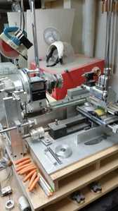
Here are some pic's to help visualize the situation:
#1 This is a view of the major Rose Engine (RE) components. Note the narrow drive belt on the left side of the headstock. It drives (variable speed) the entire headstock spindle. To its right is the fixed side of the CW. The adjustable side is not visible. Then an Index Wheel (thin blue plate) and its detent, the main body of the headstock (taken from a Sherline metal lathe), a small worm-driven rotary table and a chuck.
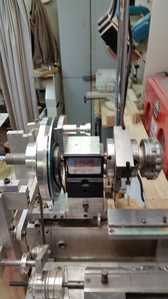
#2 The large aluminum disc is the fixed side of the CW. Attached to its side is a lever that engages a poll into the notched perimeter of the adjustable side of the CW. To adjust (phase) the workpiece, the lever is depressed to release the poll and the right side of the spindle manually rotated to the required position. The lever is then released to lock it into position.
Note that the 2 sides of the CW are also manually pressed together via a threaded rod, through the centre of the spindle, which also has to be released before the above adjustment can be made.
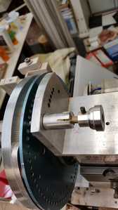
#3 Though not very clear, it shows the adjustable side of the CW and the notches with the poll in place. I intend to remove the lever/poll, the index wheel/detent and attach a cog wheel to the right side of the CW. It will be driven by a stepper motor via a cog belt.
To adjust ("phase") the workpiece you enter the number of steps required via a keyboard and the Arduino will activate the stepper. Of course it is still necessary to first disengage the 2 sides of the CW and re-engage after the stepper makes its move. The spindle drive can then be started to facilitate the cutting process but it is imperative to disengage the stepper (via "some sort of clutch") to allow the spindle to turn freely and, more importantly, to ensure the stepper does not get out of synch.
This "some sort of clutch" is the main Topic of this request for suggestions.
Coot
@coot I assume that when you say poll, you mean pawl. Other than that I am out of my depth with this, but that is some cool stuff you have there. Good luck.
First computer 1959. Retired from my own computer company 2004.
Hardware - Expert in 1401, and 360, fairly knowledge in PC plus numerous MPU's and MCU's
Major Languages - Machine language, 360 Macro Assembler, Intel Assembler, PL/I and PL1, Pascal, Basic, C plus numerous job control and scripting languages.
Sure you can learn to be a programmer, it will take the same amount of time for me to learn to be a Doctor.
Yep! That would be "pawl". Thanks for your comment. Stay tuned - hopefully someone will have a workable solution. I've been mulling over making a Taper Clutch or another (undefinable as yet) type. I just have to consider how to activate it. One thing is sure; it must be engaged to initially adjust the phasing then disengaged during the cutting process. Hmmm I just had a thought so I'd better do some sketching before I forget.
Coot
Hi Gary @coot,
I confess that mechanical stuff of the complexity you are describing is completely out of my comfort and ability zone. But out of curiosity, and on the basis that that the only silly question is the one that wasn't asked...
You say...
Traditional mechanical clutches won't do for a similar reason; there will be a few degrees of rotation before they lock-up
At my simple level, the most 'obvious' clutch is the one in my car ... which (massively oversimplfying) is two pseudo-smooth flat circular plates, that are pressed together to transmit the motion.
Why would a device based on this principle not be suitable for your application?
I am imagining that neither of two shafts/plates are rotating whilst the clutch is being engaged or disengaged, and the operating the clutch engagement mechanism is carefully designed so that it does not (accidentally) impart any rotary motion.
Assuming such a device can be made, I do not understand why there would be 'a few degrees of rotation before they lock up'
Best wishes with your project. Dave
Hi Davee
I just spent about a half hour responding and when I tried to post it went poof! and I was told that there was something wrong with my data. I will try again.
When referring to "traditional mechanical clutches" there are 2 types commonly used (not like car clutches). One uses frictional shoes that centrifugally engage with a drum and require the motor to be in motion thus relative location is unpredictable. The more common one uses a spiral coil inside a drum. The inner end of the coil is attached (indirectly) to the motor. When the motor is in motion, it expands the coil to engage it with the drum. Again, the motor must be in motion and the relative location is unpredictable.
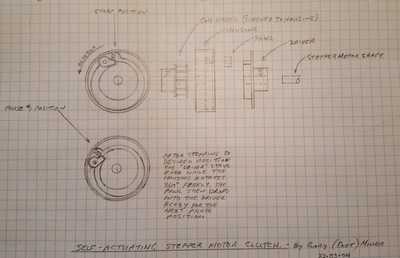
When I last posted I had a flash of and idea that I sketched out and this morning I drew a blow-up drawing to solidify it. It is self-actuating and requires the stepper motor to be stationary to function. It also allows the driven RE spindle to go through its 360 degree cutting process unhindered. When the spindle stops, the pawl will drop into the driver's indent ready for the next phasing step. I'll attach a pic for you (and others that might be interested).
Coot
I don't understand what's happening here and I haven't had anything to do with metal machining since High School (which so far back that metal had just been discovered).
What I don't understand is why you feel you need to physically disengage the stepper motor after it has finished moving to the next target spot. If you just use the enable pin on the driver, you can disable the stepper and it will then allow its shaft to turn freely.
So, I'm wondering why you can't leave the stepper attached and just disable it (via the driver) to allow it to be turned as required. As long as the rotation is not very fast or very prolonged (which might cause the stepper to act as a generator) it should be fine.
That way, no clutch would be required and the stepper could always be re-engaged with the enable pin when the cutting operation ceases with no slippage at all.
Anything seems possible when you don't know what you're talking about.
Hi Will. Thanks for your insight. Your approach might work but how can you stop the RE spindle from turning in exactly the location where the stepper must be in order to advance to the the next phasing position? It's just driven by a small, slow D.C. motor and starts and stops under manual control. Also, although my knowledge of stepping motors is a little thin, are they not magnetically held when at rest? If so, I think the RE spindle motor would need enough torque to overcome that "held" position on the stepper - tough job for a small motor. Your thoughts?
Coot
Hi @coot,
Sorry, I don't think I can help.
I understood your description of 'traditional' clutches, although I am a little less clear about your subsequent sketch. I am guessing the stepper motor causes the pawl to change to the 'engaged' position. I have the impression this means the the initial motor rotation doesn't result in rotation, but that is probably just my ignorance or maybe a small rotation can be allowed for.
Hopefully someone else can make a better contribution.
---------
By the way, if you type a message into this forum, but it fails to show when you try 'Add Reply', then try clicking on the 'Revisions' word between 'Preview' and 'Save Draft'. It is likely your message will appear below, together with an option to restore it to the editing window. Confusingly, it often shows '0 Revisions', but it may still work!
Best wishes, Dave
As I said, I don't understand the functioning of your setup, so I can't give you a precise answer.
Stepper motors apply power to the coils to produce a magnetic field which will advance, reverse or hold the position of its shaft. But, this only happens when the stepper motor driver is set to enable the motor. When the driver disables the motor, it's no longer routing any power to the coils, so the shaft is free to turn.
So, if you enable the driver, turn the stepper's shaft to the desired position and disable the driver once it's positioned; it is then free to rotate with the workpiece until the driver is enabled again. At that point, current will again be sent to the coils and they can then move to the next point of interest (and will resist movement of the shaft as long as as the driver is enabled).
Sorry, since I don't understand your setup, I'm just focussing on the stepper motor. It's quite probable that what I propose is not a valid solution (or even helpful).
Anything seems possible when you don't know what you're talking about.
I'm going to have to give this some more thought in light of your explanation about disabling the stepper allowing it to free wheel. I appreciate your interest and input.
Coot


