I want to use a DC motor with a PID controller to achieve a very specific set of speeds for a project. I've successfully used small N20 micro metal gearmotors and other DC gearmotors with 6 pin magnetic encoders with a PID controller developed in my Arduino IDE.
I've found a BLDC gearmotor with really nice specs in my price range but it runs with a 5-pin set I'm unfamiliar with and was wondering what the difference is, if there are any resources online that can help me run it with a PID controller or similar function, and if it's possible on my arduino without the use of an external potentiometer (speed provided in code)
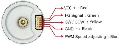
Below is a link for the BLDC motor I'm looking to use. The pinouts are as follows: VCC, FG Signal, CW/CWW, GND, PWM
https://www.robotshop.com/ca/en/24mm-brushless-dc-gear-motor-12v-95rpm.html
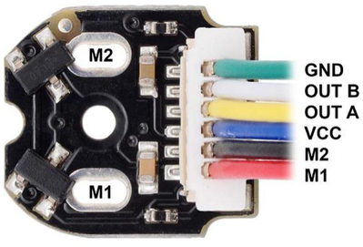
I'm used to (and current code works) with a pinout similar to the following:
GND, Encoder B, Encoder A, VCC, Motor 1, Motor 2 or a variation of those pins.
https://www.robotshop.com/ca/en/6v-101-micro-metal-gearmotor-w-encoder-cable-1500rpm.html
Any insight, tutorials, links, code, etc would be greatly appreciated - thanks!!
When it comes to motors with encoders I would like to divide I into two parts
-controlling the motor
The pwm speed adjusting pin and CW/CCW pin are similar to the input pins on the MD10C motor controller. And there is a great tutorial in the YouTube channel.The thing is I am not sure about frequency and duty cycle.I guess you can do some testing and find out.
-reading the encoder's output
In your old setup, you can find the direction by detecting which of the two pins pulled to HIGH first.
Here for detecting the direction you have asume that the motor spinning with coordination to your signal you give. So,if your telling the motor to spin in CW direction by the CW/CCW pin. Then your spinning in that direction. Which makes both system depend on each other. Which is good because it smplifi it but bad because if your motor is not working or overloaded you not be able to detect that. And for detecting the speed FG signal pin provides a pwm in which on pulse represents on increment.*Not sure what FG means.
I hope you understand. Not sure if there are libraries for kind of motor.
Atleast that's what I guess
That motor has a built in driver, that's what those 6 pins are. You will have to attach an encoder to do your normal stuff. The fg signal is a pulse that occurs once every rotation. You can use that to get your speed but it is not the same a quadrature encoder.
That motor has a built in driver, that's what those 6 pins are. You will have to attach an encoder to do your normal stuff. The fg signal is a pulse that occurs once every rotation. You can use that to get your speed but it is not the same a quadrature encoder.
I also think now the same because there is no details of the encoder just the motor and its driver
I follow youtube channel called homoFaciens. He is brilliant and one of his videos goes over the details of building a quadrature encoder from two optical sensors.
The link is https://www.youtube.com/channel/UCSBspfcqX5QuK4XBLsh1rLw


