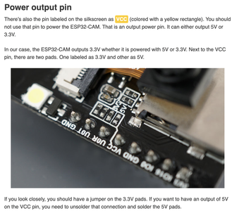
Well .... Success!
I tried it before but I just switched from 3.3V to 5V and it is now working.
Not sure what I did different from before but seems to be OK.
Regards,
Pete
Seems like a common situation. I have run my ESP32CAMS with 5V also and had success. Actually I don't think I tried 3.3V
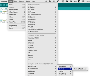
@pete Maybe, but not with a define, include maybe but highly doubt it. Are you running the Example WebServer? Is your USB cable still plugged in, that is where the power comes from initially, I will try later today to power the board externally.
First computer 1959. Retired from my own computer company 2004.
Hardware - Expert in 1401, and 360, fairly knowledge in PC plus numerous MPU's and MCU's
Major Languages - Machine language, 360 Macro Assembler, Intel Assembler, PL/I and PL1, Pascal, Basic, C plus numerous job control and scripting languages.
Sure you can learn to be a programmer, it will take the same amount of time for me to learn to be a Doctor.
@pete Since when you upload the sketch it is over the 5V USB cable, I don't know how you got the impression it was 3.3V? True, there is an LD1117 converting 5V to 3.3V onboard the board but the external supply is 5V. Glad to hear you are up and running, BUT be very sure of your voltages. It is EXTREMELY common for new folks to fry their 3.3V card by applying 5V. The RandomNerd web site is a good education resource.
First computer 1959. Retired from my own computer company 2004.
Hardware - Expert in 1401, and 360, fairly knowledge in PC plus numerous MPU's and MCU's
Major Languages - Machine language, 360 Macro Assembler, Intel Assembler, PL/I and PL1, Pascal, Basic, C plus numerous job control and scripting languages.
Sure you can learn to be a programmer, it will take the same amount of time for me to learn to be a Doctor.
Did everyone not watch Bill's video and read the blog ?
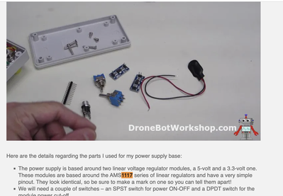
That part that gets hot beside the reset switch is the AMS1117 LD voltage regulator. Get out your magnifying glass and you will see. If it outputs 3.3V, what must it's input have been? What is the USB voltage?
5V in 3.3V out. A VERY common arrangement. There is even more, you can change the VCC out if you want to power other devices with either 5V or 3.3V. NOTE, advanced use, what is current supply??? what is demand??? That is why we read spec sheets. Class dismissed LOL
First computer 1959. Retired from my own computer company 2004.
Hardware - Expert in 1401, and 360, fairly knowledge in PC plus numerous MPU's and MCU's
Major Languages - Machine language, 360 Macro Assembler, Intel Assembler, PL/I and PL1, Pascal, Basic, C plus numerous job control and scripting languages.
Sure you can learn to be a programmer, it will take the same amount of time for me to learn to be a Doctor.
Hi @pete,
ESP32 and power supply arrangement problems seems to be endemic. I am pleased that you have managed to make it work, but due to the design of the ESP boards, the description of your cure is ambiguous.
Sorry, this is a bit of a sermon ... it is provided in good faith.
-----
On the positive side, I am pleased you are looking at the power arrangements, rather than disabling the brownout messages, even if the ESP devices may appear to be on the 'over cautious' side with respect to detecting the condition. Logic circuits are fairly robust against noise on power lines but if the power voltage goes too low for a moment, there is a risk that somewhere in the system a '1' will become a '0' (or vice versa), and if that logic state happens to control a microcontroller program, then it is liable to completely 'lose the plot' and start executing random instructions, etc. A common mitigation is to have a circuit that monitors the power, and 'raises the alarm' if it spots the power line voltage going below a predetermined threshold. Many embedded systems simply reset the processor, but it seems the built in monitor of the ESP32 is able to report it in the form of a 'brownout' message, presuming the processor is still able to transmit the message. I am aware it is possible to disable the message, but that is a bit like taking the battery out of the smoke alarm because you burn the toast every morning.
-------
The popular ESP boards are also confusing in that they have both 5V and 3.3V pins, but the reason is slightly harder to find, and unsurprisingly, some comments on the web are just wrong.
The ESP32 (and ESP8286) processors have a maximum voltage limit of 3.3V on ALL of their pins, including those used for programming. This is in contrast to many, but not all, of the 'traditional' Arduino boards, for which the limit is 5V. In addition, USB supplies power at 5V (or more with the recent USB-C standard) and the data signals are 5V max as well. Hence, care is needed when connecting an ESP board to USB.
The easiest case, is for those ESP boards that have USB socket built in. These boards contain the circuitry needed to convert the incoming 5V power and 5V data lines to 3.3V equivalents for the ESP processor to access. The only thing to beware is that the 5V supply from the USB plug may be routed to a 5V pin on the board .. just make sure it is not connected back to one of the ESP processor GPIO pins - for example if you connect a GPIO pin to a LED or switch, power the switch/LED via the 3.3V outputs, NEVER the 5V output pin.
-----------
The more confusing case is when the ESP board requires an external board, usually (somewhat incorrectly) referred to as "FTDI". The ESP32 CAM boards are usually in this category. These "FTDI" boards are often 'universal' in that they are able to drive both 5V logic boards (e.g. many Arduinos) and 3.3V (e.g. ESP32 CAM) ... but they must be switched or jumpered and wired accordingly.
For a card like the ESP32 CAM, the DATA signals should always be set to 3.3V. I have heard reports of it only working when set to 5V ... this may be the result of some "FTDI" cards with substandard chips, or badly marked boards confusing the user but it isn't a good sign, and risks damaging the ESP32 processor.
Powering the ESP card via the "FTDI" adaptor board often presents two options:
- 3.3V output from "FTDI" adaptor to 3.3V input to ESP32 card
- 5V output from "FTDI" adaptor to 5V input to ESP32 card
In theory, they amount to almost the same thing. Both the "FTDI" adaptor board and the ESP32 card have a 5V to 3.3V regulator, usually AM1117. The only 'obvious' difference between the two options, is which of the two (probably identical) regulators supplies power to the ESP32 card. I think the 5V option has marginal advantages when the effects of wiring and power sharing are considered, and that may help your case. I couldn't see any practical performance difference but other might have different experience.
-------------
So in summary, if "I just switched from 3.3V to 5V" means you adopted the 5V power arrangement I just described, whilst keeping the data lines at 3.3V, then "great".
However, if the data lines have also been set to 5V, then be aware it could damage your ESP, as if the FTDI board is truly trying to drive 5V signals, then the ESP processor will be having a torrid time.
---------
And as an aside, regarding your experience using a USB hub, bear in mind that many 'powered' hubs only supply a limited current, and many USB leads have very thin copper wiring, both of which can exasperate the rather power greedy habits of the ESP32. (Bill makes more extensive helpful comments in his ESP32 CAM video.)
---------
Best wishes and good luck, Dave
@davee EXCELLENT explainer, more thorough, complete, and accurate than my hasty attempt. We should bookmark this for future responses when it surely happens again. Admin? can that be done?
First computer 1959. Retired from my own computer company 2004.
Hardware - Expert in 1401, and 360, fairly knowledge in PC plus numerous MPU's and MCU's
Major Languages - Machine language, 360 Macro Assembler, Intel Assembler, PL/I and PL1, Pascal, Basic, C plus numerous job control and scripting languages.
Sure you can learn to be a programmer, it will take the same amount of time for me to learn to be a Doctor.
Thanks Ron, Thanks Dave,
Dave I have to study your description some more.
But basically I was just following Bill's video and used the FTDI Bill used (It looked the; same-got it from amazon I think by HiLetgo). I set the jumper on the FTDI to 3.3V and wired just as Bill diagramed with the VCC going to the 3.3V pin on the ESP32-CAM.
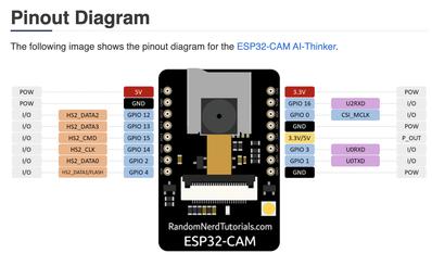
I tried this before I think without success I thought but today after getting the brownout message on both ESP32-CAM boards at 3.3V I moved the VCC over to the 5V pin and set the FTDI jumper to 5V. This worked. I've seen this on the internet after doing a search and tried it before. I also thought this was suggested later by Bill in the video but I'm going back to watch it now. It was a little confusing because of the warning early in the video to have it (the FTDI) Jumper'd at 3.3V. I think you explained how it should be Dave, but I have to read through your message again.
I have handled these boards so much now I am surprised they still work.
I went to 5V today because I bought the special FTDI from ADAfruit and was getting ready to try it but it is set at 5V as received but you can solder it to supply 3.3V. I have a couple Arduino Pico boards (3.3V and 5V) that I want to try with an FTDI so I will need to do this for one of them anyway. But I thought lets try it with the HiLetgo board first. I get impatient and often use the hammer approach.
I need to get the bard(s) to work independent of the USB power supply. My first try this morning did not seem to work although when I hooked the board back up to the USB and Arduino IDE the sketch was still loaded and working.
Thanks Ron, Thanks Dave.
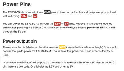
@pete Yes, it can be confusing. Most Arduino boards are 3.3V but this one is special. You supply 5V on the pin marked 5V and an internal voltage regulator converts that to 3.3V for internal use. So 5V selected on the FTDI, the FTZDI 5V pin to the ESP32-CAM 5V pin and it should be good to go. Do NOT use the VCC pin, that is intended to supply either 3.3V or 5V OUTPUT limited current to any supporting circuits. I don't think you ever did that but thought I would mention it for completeness. Once sketch is loaded and you want to deploy, a 5V USB charger will power the camera. I am not sure at the moment if it has to be 1A or 2A but check the plugs and use a 2A to be sure. The board datasheet will specify total board amperage, the WiFi is a power hog.
First computer 1959. Retired from my own computer company 2004.
Hardware - Expert in 1401, and 360, fairly knowledge in PC plus numerous MPU's and MCU's
Major Languages - Machine language, 360 Macro Assembler, Intel Assembler, PL/I and PL1, Pascal, Basic, C plus numerous job control and scripting languages.
Sure you can learn to be a programmer, it will take the same amount of time for me to learn to be a Doctor.
Hi @pete,
As I mentioned, you are not the first to report it only works with 5V data drive selected, although most people seem get to work with 3.3V setting. However, every single bit of documentation I have seen about ESP8266 or ESP32 from Expressif says 3.3V only .. not 5V tolerant. And presuming they follow normal logic chip conventions, that is a very reasonable and normal approach. A few chips with specfic tasks, like long distance wire data transmission and analogue amplifiers, are more tolerant but it takes at lot more silcon area etc. to build the capability in.
As you will appreciate, these 'products' are far from uniform, especially the "FTDI adapters", often being clones of clones, each different clone trying to save an extra cent or two, to make them at less than the price of a cup of 'posh' coffee. So in the absence of personally testing such a combination, I can only make bad guesses as to the reason. Maybe it is case of 'two wrongs getting closer to a right', with the data waveforms being distorted by poor electronics.
Good luck, Dave
First computer 1959. Retired from my own computer company 2004.
Hardware - Expert in 1401, and 360, fairly knowledge in PC plus numerous MPU's and MCU's
Major Languages - Machine language, 360 Macro Assembler, Intel Assembler, PL/I and PL1, Pascal, Basic, C plus numerous job control and scripting languages.
Sure you can learn to be a programmer, it will take the same amount of time for me to learn to be a Doctor.
I guess from my limited reading the basic ESP32 has been evolving itself and had similar quirkiness issues. I've tried several as I mentioned, and they seem to work just fine.
I have the Nano IOT33, which I guess is also based on the ESP32 chipset, and several RP2040 boards to try out. But first I am going to go back to study Bills videos on the 555 timer and logic chips. Going back in time. But I'm on a rather steep learning curve here.
Regards, Pete
@pete IOT33 is Arduino, ESP32 is Espressif, no relationship. Now the Strawberry Pi PICO is the wildcard, they created a microcontroller called the RP2040 to go on their new micro computer and it's also sold to many other companies to be re-packaged with various supporting circuitry but more along the lines of micro controllers like ESP and Arduino.
First computer 1959. Retired from my own computer company 2004.
Hardware - Expert in 1401, and 360, fairly knowledge in PC plus numerous MPU's and MCU's
Major Languages - Machine language, 360 Macro Assembler, Intel Assembler, PL/I and PL1, Pascal, Basic, C plus numerous job control and scripting languages.
Sure you can learn to be a programmer, it will take the same amount of time for me to learn to be a Doctor.
Actually, in following Bills video he describes the (Arduino) Nano 33IoT having WIFI and Bluetooth capability from ublox NINA-W102 Bluetooth and WIFI which itself is based on the ESP32 Chip. The RP2040 boards I have are microcontrollers from Raspberry PI, Adafruit and Arduino.
Hi Ron @zander,
The ESP32 CAM does seem to be a 'special case' in that it is particularly susceptible to power problems. I have yet to personally venture into other ESP32 boards, but the CAM maybe more 'obvious' because it has both the camera (including processing) and WiFi to cope with. WiFi current demands are known to be high when transmitting. I suspect some of the problems will recur with ESP32s generally.
Of course all ESP32 variants and all ESP8266 variants only tolerate 5V as far as their voltage regulator input ... all of the rest, such as processor I/Os, programming data pins etc, must be strictly 3.3V maximum. This is different from many, but not all, archetypal Arduinos.
Best wishes, Dave
(NB Ron, your finger slipped in your previous post ... you said "Most Arduino boards are 3.3V " .. I am sure you meant "5V" ... to my ongoing embarassment, I know how easy it is to make a slip.)

