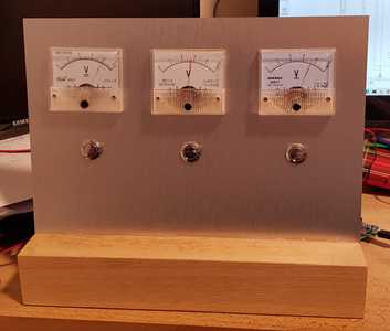
As a Software Developer, for 20+ years, I've been meaning to learn Electronics for about a decade and after many false starts I've been able to finally give it the time it deserves. My first project was an arduino clock, using 3 volt meters for Hours, Minutes and Seconds (I'd post a photo but I'm not sure how). I learnt lots from it. The main thing being that you don't get 5V from the pins. The second things was don't buy parts until you know what voltage you'll get from the pins.... 🙄 I guess I need to learn to read the documentation. It worked out well and I mounted the meters on a slanted aluminium panel which was slotted into an oak base.
One of the things which I struggled to pick up was the interaction of parts in a circuit. I could understand them in an isolated way but working out how one part of the circuit was affected by another really threw me for a good while. Especially since most books/online articles go from individual parts then to very, very basic circuits to "boom" - complexity without the breakdown. If there is to be some videos for beginners could you do one or two on that please? Have a complex circuit, by all means, but break it down (highlight a section) discussing that and then how it relates to the whole.
Anyway I'm hoping to learn off everyone here, I've really enjoyed the 10+ videos I've watched so far, and look forward to watching them all. Bill's instructions are simple and straight forward. Thank you. I don't subscribe to many YouTube channels but I had to for this.
Cheers,
Titch
PS:
If anyone has any Software questions, hopefully I can help. My experience covers C, C++, C#, Javascript (most of the frameworks). I've even done lua before but I'm rusty on that.
So is this the project?
https://create.arduino.cc/projecthub/mircemk/arduino-analog-panel-meter-clock-a08777
One of the things which I struggled to pick up was the interaction of parts in a circuit. I could understand them in an isolated way but working out how one part of the circuit was affected by another really threw me for a good while. Especially since most books/online articles go from individual parts then to very, very basic circuits to "boom" - complexity without the breakdown.
Hardware and software are complementary. You can simulate hardware in software or you can embody software as hardware. Just as in software you have modules made out of modules all the way down to your fundamental statements so too a complex circuit is made out of modules made out of modules all the way down to discrete components.
Like software a hardware module has an input and/or an output. Just as in software you can think of it as being made out of black boxes. You can use a function (or object) without having to know how it works only how to use it with your own software, so too with electronics.
Some hardware modules are so useful they are packaged in a chip such as the 555 Timer or Op amps and so on.
So is there any complex circuit you want to give as an example?
(I'd post a photo but I'm not sure how)
When typing a post you should see a paper clip symbol and the word Attach Files
@robotbuilder I didn't actually see that but thanks for pointing me towards it. I saw a photo of one in Hackspace magazine and thought I'd give it a go. I'm kind of glad that I didn't see it beforehand because I learnt a lot more by doing it from trial and error than I ever would have following it.
One of the things which I struggled to pick up was the interaction of parts in a circuit. I could understand them in an isolated way but working out how one part of the circuit was affected by another really threw me for a good while.
Exactly this is where I stand at the moment. I mean, I know what a resistor does and also what a capacitor does. But when it comes to how and what measurements they should be to go together... well, I have almost always to rely on those circuit diagrams of others found on internet and even then, as I start, I keep my fingers crossed that the ciruit is not going to be wrong or blow up something. Not lucky always though.
I've been meaning to learn Electronics for about a decade and after many false starts I've been able to finally give it the time it deserves.
I am interested to know your start points for sure. I had asked on another thread and I received a few PDFs. But during the few weeks that have passed since then, I have never been able to give them the time I should have.
Welcome aboard. You are surely going to enjoy your stay here. 🙂
Life is exploring and learning
@sid give me a couple of days to collate some sources and I'll post them here.
@robotbuilder thanks for your help with attaching files. This was the clock before I added new dial backgrounds with H, M, S. I used a DS3231 to keep the time do if the clock was turned off it wouldn't lose time. The buttons are for forwarding the relevant dial, thereby setting the time. Also used was an ATMega328 with a Arduino bootloader. I'll find some circuits that bamboozle me.
Cheers,
Titch
That's really cool
If you hadn't told me I would never have guessed it was a clock
What time is it saying now, maybe about 9:40 or so ?
@sid so basically I read and in some cases re-read the following books. In no particular order:
Starting Electronics - 3rd Edition - Keith Brindley
Beginners Guide to Reading Schematics - 4th Edition - Stan Gibilisco
How to Diagnose and Fix Everything Electronic - 2nd Edition - Michael Jay Geier
Electronics for dummies - Gordon McComb (I'm in the UK and this is the UK version. I don't think it's that good)
They're the hard copy books. I've got a few on my Kindle as well.
At one point I was trying to understand all the science behind every part and I came to the conclusion that I was being daft. I was overloading myself basically and came to the conclusion that I needed to just muck around with the basic concepts and build from there.
I also watched and re-watched a lot of videos on YouTube from the following:
DroneBot Workshop - not sure where I'd be without this site
element14 presents The Learning Circuits - the basics plus some practical zany applications for the concepts they've done videos on. The main sites have some good videos as well.
AddOhms - has since stopped and now presents at element14
Afrotechmods - hasn't come out with new material, on YouTube anyway, for a while but I liked
One I've found since, which I really like is:
bigclivedotcom - he buys from the UK equivalent of the Dollar Store, takes the item apart, shows blown up photos of it and discusses the circuits. He's got a great laid back presentation style.
Also I subscribe to HackSpace Magazine. Some of their early basic articles really helped me. You can get all their issues as pdfs for free but I like the paper copy in my hands 🙂
Hope something from this list might help,
Titch
At one point I was trying to understand all the science behind every part and I came to the conclusion that I was being daft. I was overloading myself basically and came to the conclusion that I needed to just muck around with the basic concepts and build from there.
This seems to be a sage tip (at least to me, as I always have wanted to know more and now that you mention this I feel probably this is the reason I have failed to make any notable or worth mentioning progress - I got into the habit of finding more rather than using the info at hand).
Thanks again for this wonderful list of books and Videos. Bookmarked this page and also noted down the list of books. Hopefully, I will find some time everyday for a read.
Life is exploring and learning
@robotbuilder
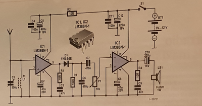
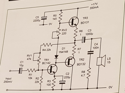
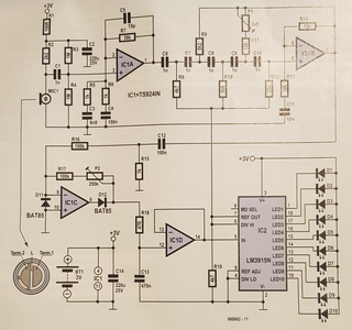
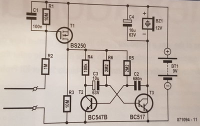
Apologies for taking so long to get back, I started a new job and got side-tracked. So I eventually went back through some old things and found some circuits which I was struggling to breakdown. These are pretty basic components but were complex enough that I'm sure they could be broken down in to sub-sections, I just wasn't sure where to start. Sometimes it's like chicken and egg, knowing which part affects the circuit first or whether it's all as a hole. Any I attach some circuits from some old EPE and Elektor magazines.
It might be worth opening it up as a general question to the forum or your YouTube subscribers - send in circuits you don't understand and you could break them down for everyone.
Cheers,
Titch
It might be worth opening it up as a general question to the forum or your YouTube subscribers - send in circuits you don't understand and you could break them down for everyone.
I don't have any utube videos perhaps you are thinking of Dronebot?
If there is any interest in the topic as to how to dissect and read a circuit the moderators could move this to another forum?
Probably the text that came with these circuits would tell you something about how they worked?
Firstly my skill set in electronics is limited as I am self taught and it was a hobby I haven't spent time with for decades!
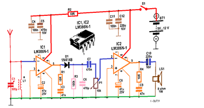
The first circuit is a radio receiver although I have not seen that design before. When reading a circuit you can trace the signal from one module to another. The first module is a tuned circuit C1 and L1. When radio waves pass through a conductor the electrons move back and forth like a cork on water waves. The tuned circuit acts like a tuning fork. Hit it with a voltage and it will "ring" at a certain frequency. In this case the choice of L1 and C1 values act to suppress all but a certain frequency of radio waves. C1 is used to tune the circuit to different radio frequencies (radio stations).
The output of the tuned circuit module is fed into the LM386 amplifier the role of which I am uncertain in this case. The diode D1 at the output blocks the negative part of the wave (half wave rectifier). The R3 and C6 make up a RC filter which averages the radio wave out to produce the carrier wave (audio signal). The radio wave (high frequency) is amplitude modulated by a lower audio frequency at the transmitter. C7 is a decoupling capacitor, that is, it decouples the DC component from an AC component for the next stage. P1 is a POT (variable resistor) or volume control that divides the voltage between the output and ground to feed into the next LM386 amp. The C10 is another decoupling capacitor that provides the AC audio signal across the speaker. The speaker is an inductor.
Now I don't really get the role for the first LM386 or R2. The capacitors C4,C5,C11 and C12 would filter out signals developed over the battery's internal resistance due to varying current demands.
The BLUE lines are the signal lines. If you had an oscilloscope you could touch them with the probe to see how the signal changes at each stage.
Now if I have anything wrong perhaps a more knowledgeable forum member can enlighten us.
I will elaborate on the other circuits if wanted or others can?
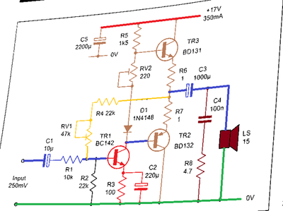
The second circuit is an audio amplifier.
The third circuit displays sound waves of some kind on the dot bar display.
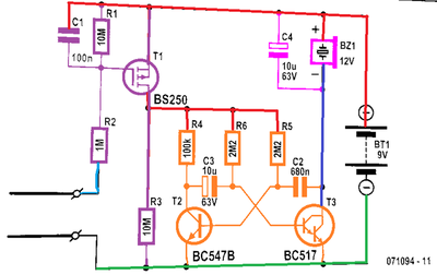
The fourth circuit is a buzzer circuit that is turned on/off when the probes provide a voltage to turn the MOSFET on which in turn provides power to the square wave oscillator circuit that drives the buzzer.
right click choose open link in new window for enlarged view
@robotbuilder, this is epic, breaking it down with those colours really is great, to go along with your descriptions is much appreciated. Thank You. I wish there was more like this.
edit: @robotbuilder, yes please elaborate, I'm really enjoying reading what you put. Also do you have a coloured version of third circuit - dot bar display one please?
All the best,
Titch
The color versions were made after I binarized your images. The dot bar circuit was not evenly lit although to the human eye the lighting seems even all over. The best way is to scan an image. Text that came with the circuits would probably also provide useful information.
Ok I will elaborate on the other circuits tomorrow, it is 10 pm here and I am feeling tired.
Another way to understand circuit operation visually is to trace the current paths with different colors. Many circuits are dynamic so you need an animation or at least a number of frames. I see there are utube tutorials you can watch that do just that. Getting an education is so easy with the internet compared with how it used to be buying expensive books!
@robotbuilder, thank you again. Is that any of those youtube channels you'd recommend?
Thanks for this - I have the same problem in that I look at a schematic and wonder what each piece does and how it works.
A much more embarrassingly fundamental question would be: R3 and C6 are tied to ground. How, therefore, do they affect the signal into C7? There are "forks" in the circuit, if that makes sense.
Be gentle - I'm a software guy! 😆


