Creating a current variance through a MOSFET, between VGSmin to VGSmax to charge NiMH battery.
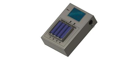
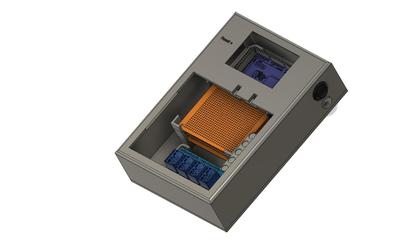
I'm brand new to this forum, but Joe has suggested I post here to get help for this. I've designed a battery charging holder in #Fushion360, as shown below, for charging both NiMH (AA & AAA) & Lithium batteries. I've designed a smaller 3.5" display holder to test my code b4 printing the full-size holder.
Below is the code to detect the insertion of the different holders, & to set the current type of battery being charged.
THIS is where I've become bogged down. My thought was to rely on the MOSFET'S ability to alter it's appearance as a resistor, between VGSmin(2V on IRF540) & VGSmax (4V). I'm also using INA219s to do the critical part of checking the current through the load, so my code can either increase or decrease the current through the load to approx. C/8 (with a 2500mAh battery charging at 312.5mA).
I've substituted for my load, a 220ohm resistor & LED, which will either be dim(at VGSmin) or bright(VGSmax) when I drive a PWM figure from the Arduino.
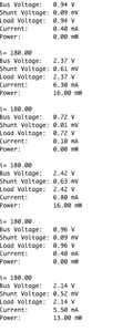
This is where I've faltered. When I enter manually a PWM, somewhere in the VGS range, I simply can't get the INA219 to detect the current with ANY repeatability. It is driving me crazy(well, more crazy than I naturally am). You can get two readings only 10 seconds apart, that
can be half or more either higher or lower than the last. It's frustrating me!
Can anyone suggest what I'm doing wrong? Is it a problem with my code, or the MOSFET, or the iNA219 i2C current measurement, or am I doing something fundamentally wrong?
Hoping someone can help,
Christine
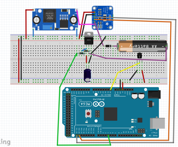
It looks like the MOSFET is in the wrong location. In the current configuration the FET will be turned on hard when the a PWM through a resistor charges the capacitor. Even between PWM pulses the capacitor keeps the FET on.
If I understand what you are trying to do I believe the FET should be between your current sensing devise and the diode that feeds the battery. This way the FET's source will track the gate voltage and varying the PWM will control the current flow. You will also need to connect the negative end of the charging battery to ground.
There are a couple of other minor changes needed, I would put a diode in the PWM line before the capacitor and add a high value resistor (i.e., 1M ohm) to bleed the capacitor since the FET gate resistance is so high. The way it is configured now the output of your MCU will charge the capacitor during the pulse and discharge it when there is no pulse. This will cause significant ripples in your charge current.
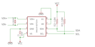
I couldn't find a schematic for the INA219 to ensure it has pull-up resistors on the I2C lines. I know it is working in your sample provided but to ensure you don't have intermittent problems add 10K pull-up resistors to the I2C lines.
Thanks for replying to my query, I am frustrated no end by this.
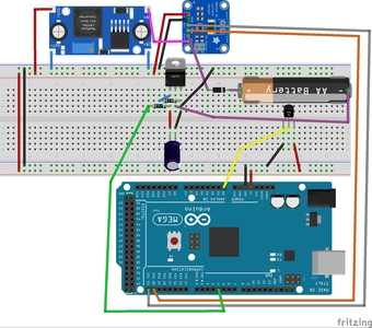
1/ I'm using a 100ohm resistor in series with the #Gate, I wanted to try & smooth out the PWM pulses, so I've got a 10uf bipolar cap attached to gate & GND. I've removed the capacitor, but to no effect. The resistor between #gate & #Source is a 1K ohm, if that makes a difference?
2/ It perhaps is unclear, but the left top board is a LM2596, which gives me the voltage to charge the battery, & the board at top right is the ina219. That path from the LM2596, goes first through the current sensing ina219, then through the schottky diode, through the battery, through the #Drain of the IRF540, & through the #Source of that, to GND.
3/ The ina219 does have pullup resistors (see diagram attached), so that should not be a factor.
4/ I've increased the #Gate resistor, to 1M ohm as you've suggested, but as you can see, this doesn't have any effect either!
I think you can see my frustration here. I've been at this for two days, & have been unable to get consistent readings, so can't charge a battery, when I might be under, OR over charging the battery. Thanks for your help though, I at least appear to be doing it the way you would have done.
thanks,
Christine
Oh Ruplicator,
I think we might be at cross purposes here,
the #Battery shown, is actually the #Load. This project is to charge batteries, & I've (for testing purposes) replaced the rechargeable battery, with a resistor & LED, to replicate the load, with a consistent current draw!
Sorry, I'm new to #Fritzring as well, & I just grabbed the first 'battery' I came across, to layout my design!
My bad,
Christine
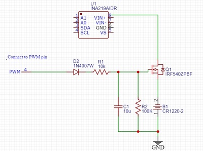
I believe I understood your the layout and the intent of your circuit. Unfortunately, I may not have been clear on my suggestion to fix your problem. I'm attaching a circuit segment that will hopefully make it more clear. I can't be sure of the values and you may need to tweak them to get the smoothest signal from converting a PWM signal to a analog signal. Hang in there... if this stuff was easy everyone would be doing it. 😉
Sorry, in my rush it looks like I connected the MOSFET to the wrong output lead of the INA219. Oh, and also be careful running your test circuit in the loop() section, as the processor is quick enough to issue a new analogWrite before a full cycle of the PWM. I see you have a delay(50); and it should be good enough.
Hi again @ruplicator
NOW I'm REALLY confused, I'm not sure what the heck I'm doing!
Isn't the #load(the CR1220-2 you've shown) supposed to be on the high side of my IRF540 n-channel MOSFET(beneath the ina219, & above the #Drain)? I've built it as shown in your diagram, but the LED barely glows, no matter the voltage applied to the #Gate. So, I've replicated your schematic, in all but position of the load, which sits between the the voltage source, & the #Drain of the IRF540. (As an aside, which program would you suggest to produce schematics. I'm thinking of using #Eagle, since it's from the same company as Fusion 260 which I'm learning to produce .stl files for my Prusa?). But, as is becoming my new reality, for the exact same current, the ina seems to be making up currents as it feels like!
I've been over everything I can find, by Bill @dronebot-workshop, & other sources on the web, but have not yet found something that actually works. How can I control the current through a load, when I can't find what that current is?
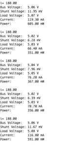
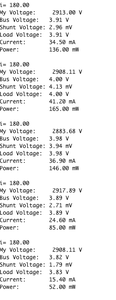
Just as an example, when I output a steady 180 PWM signal, as you can see, I get rock-steady 25.90mA on my Fluke; while the ina219 is all over the place. This according to my math, SHOULD be 25.8mA, meaning the manual current measurement is to be believed over the Arduino current sensor. Next I'll be tearing my hair out in giant clumps, & wearing a pair of tissue boxes for shoes! 🤪
Hope you can further help,
Christine
NOW I'm REALLY confused, I'm not sure what the heck I'm doing!
OK, maybe we can kill two birds with one stone. I use this software (SimulIDE) not so much for schematics (It a little bit more like Fritz) but the real power of it is that it will let you simulate circuits. In my early efforts of my current project I used it a lot to work out a number of discrete components along with IC and the Arduino Uno. It saved me lots of time as I could breadboard on the computer and quickly adjust values and once I got it working there I moved to the breadboard. Like most free software it's not perfect and in all honestly I had trouble getting it to simulate your Mega. But I've been able to work around its quirks and found it usefull.
https://www.simulide.com/p/home.html
I usually use EasyEDA for schematics. It's free and quick to learn and if you ever want to move your design to a custom circuit board your a head of the game. I recently completed a design in EasyEDA and used it to design a custom board. My first!!! I don't know if it was luck or the ease of use but after installing the components it worked with no problem.
P.S. Have you check the INA219 with just a load connected to it to see if it is operating correctly? Maybe it has problems or something up stream.
Isn't the #load(the CR1220-2 you've shown) supposed to be on the high side of my IRF540 n-channel MOSFET(beneath the ina219, & above the #Drain)?
Nope. But it might be easier if you have a NPN transistor and use it in place of the MOSFET. The emitter voltage will track .7 V lower than the base. This makes it very easy to control current using an integrated PWM signal.
NO HAIR PULLING!!! You will regret it when your my age. 🙄
Christine,
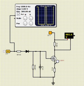
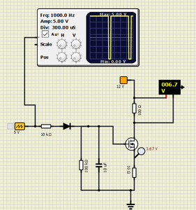
I had some time and set up a circuit for your battery charger in the SimulIDE software. I had one revelation, I don't know the voltage that comes out of your INA219. Also the voltage produced by the PWM integration is not enough to activate the MOSFET with the battery connected to the source as I proposed.
The attached pictures are a snapshots of the simulation running basically your configuration but with the addition of a 10 ohm resistor between the source and ground. This provides just enough negative feedback for the circuit to be stable. The two pictures are of a 20% duty cycle and a 90% duty cycle. You can see the voltage across the simulated load resistor.
An additional thought, you could use 3 ADC inputs to measure voltage at the top and bottom of the battery and at the top of the 10 ohm resistor and and save your INA219 for another project. You can use the voltage across the 10 ohm to calculate the charge current and subtract the voltage at the bottom of the battery from the top to calculate battery voltage (This would require some additional voltage dividers to get the voltage in the range of your ADC.)
Hi.
I thought of using analog inputs in exactly the way you suggest. I quickly decided this would be impractical.
I have designed my battery charger case to hold 4 batteries, & the reason I don't want to go the the analogRead(A0) etc. is because I want EACH battery to be treated separately, & charged independently to the battery in the adjacent slot. It has always annoyed me that battery chargers insist you charge batteries in pairs, even if 1 is only partly discharged. But this would mean the use of a LOT of analog inputs.
I'll try the setup you modeled. & would LOVE it if it works(I'm at work now, so can't try it till I get home.)
I am blown away by the software you're using. I've downloaded it. & will look at it tonight. Was it difficult to learn, fusion 360 took me weeks before I could design anything non-trivial!
I've ordered some ACS712. & some Max471 voltage & current sensors, & HOPE one of these works. I chose the ina219, since you can daisy-chain them, with solder bridges on the ina219 for different addresses, & only 2 leads for #scl & #sda, thus greatly reducing the ports of the Arduino being used.
As it happens, I already have some 10ohm 5W resistors, as I too had thought of using them to obtain voltage across them, & then determining current. but apart from the analog inputs needed, it is SUCH an inelegant solution. I blame my uni education for always making me try to get the most done, with the smallest parts count.
Not that I'm desperate(MUCH), but I've ordered a stack of MOSFETS, apart from the IRF9540, including IRF3205, IRLZ44, IRF3205, IRF5305.
I too thought of using a BJT, & actually ordered some TIP120, before I moved instead to MOSFETs. Would that be a better solution, or should i keep going with my current(he he) MOSFET design?
Thank you so much for your continued help, I'll try your schematic tonight, I'm fast approaching lunacy with mine, but it SHOULD work, everything I've learnt tells me it should, but I'm fast learning that real life is not as easy as the math would suggest!
Christine
Hmmmm, I thought you were using an Arduino Mega. I haven't used that MCU but I thought it had 15 analog to digital converters. If that is true then monitoring 4 batteries only takes 3 for each battery (3 less if you use a common supply source) and maybe some resistors for the voltage dividers. Rather than 4 INA219s. But I understand your method is much cleaner from a design point. You mentioned you look at design from parts count and I guess I tend to look at it from a cost perspective... different strokes. 😊
What voltage is coming out of the INA219? And with what maximum current are you planning to charge the batteries? And the maximum voltage across the battery being charged? The reason I ask is I want to make sure there is enough voltage to charge the battery at maximum current given the addition of the resistor in the MOSFET source circuit. The final value for that resistor may need to be a lot lower than the 10 omhs in the test circuit if there is going to be significant charge current.
I am blown away by the software you're using. I've downloaded it. & will look at it tonight. Was it difficult to learn, fusion 360 took me weeks before I could design anything non-trivial!
No, it seemed very intuitive to me and there are tutorials on there website and dozens of examples with the software. If you run into a snag give me a shout as I've used it quite a bit now.
I too thought of using a BJT, & actually ordered some TIP120, before I moved instead to MOSFETs. Would that be a better solution, or should i keep going with my current(he he) MOSFET design?
In this configuration I think it is a toss up. I'm very old school and understand the engineering behind the BJTs much better so I naturally have a bias.
"naturally have a #bias"(to BJTs). 🤣 🤣 sorry. I've almost literally gone CRAZY over this.
Also. finally, I T W O R K S!!!
******I finally have a current reading that is BOTH in accord with my Fluke, & is rock steady******
I really didn't want to try and use analogRead() to get voltages, I wanted also to use 4 analog inputs for temperature probe transistors, & that's what caused me to think of the ina219.
I have thought of using 1.6V to each of the four battery holders, as that is the recommended voltage given by Panasonic for their Eneloop Pro(I have LOTS of these floating around here). My idea was to turn off the MOSFETS, & then analogRead() the voltage of the battery to determine it's charge completion(I also will check for temperature & time values to do the same).
As to current, I am thinking something like C/10 or perhaps c/8 which for the eneloops, is something between 250mA & 312.5mA.
This is why I wanted to keep just the load on the #Drain #Source path, in the hope I can get something like this charge level through #VGSmin to #VGSmax.
I'll try using Simulide this weekend, assuming I can get something like compliance by my MOSFETs, to get battery charging for NiMH batteries. After this, I also want to try charging single 18650 Lithium rechargeables too. I've no idea whether that will be easy or hard, I've just been consumed by THIS part of the final circuitry.
I know you can use TP4056 to charge Lithiums, but I'm intent here, in getting practice & learning both #Fusion360 & #Arduino, which you can only get if you go back to first principles!
Again. THANK YOU,
Christine
I T W O R K S!!!
I'm so glad!! Congratulations. Now that you got this far the rest should be all down hill.
Unfortunately, my project has hit a wall. I'm working on a weather station but the main feature was using ultrasonic transducers to determine wind speed and direction. I'm using the transducers out of 2 HC-SR04s giving me 4 transducers connected through an analog multiplexers and fed back into 1 HC-SR04 circuit board. This allows me to orient the transducers at the 4 points of the compass, with each pointed at the opposite transducer. Then I run through TX from North to RX South; then TX from South to RX North, then repeat the process for East and West. By subtracting the opposing delay signals I can calculate the speed of the wind and which direction it is out of.
Now for the but... I tested with a single pair of transducers and was surprised that such inexpensive units could provide good resolution. With no air motion I was able to consistently measure to the uSec and stability and repeatability were tolerable. So I completed the software, 3D printed the housings, and sent my circuit design off for a custom PCB. I finished assembling and testing the circuit board earlier this week and mounted all the sensors (temperature, humidity, barometric pressure, rain measurement, UV Index and particle concentration... oh yes and the wind sensors) I set it up and let it run a couple of days on my back patio. All was working great. Then the wind readings started getting erratic and one of my multiplexer chip failed due to heat sensitivity. I had spares and replaced it but that wasn't the whole problem. It looks like my polling the transducers every 4 seconds 24 hours a day for 3 three days destroyed the transducers.
This is a real bummer. I've worked on this for about 3 months and even though all the other sensors work fine the sonic wind detection was to be the crown jewel. Yeah, I could buy better ultra sonic transducers but their in the $20 range and 4 of them would cost more than a quality anemometer. And I still wouldn't know for sure if the concept will work long term. Sorry just bummed out right now, I threw in the towel earlier today and haven't gotten over it yet.
Gosh, I'm SO sorry you've found yourself at an impasse.
I want to learn how to use a PCB design software package & have them professionally manufactured. I wasted THREE days, trying to transfer my design to a PCB board, & got nowhere, other than destroying a current sensor from a short I didn't find it b4 powering it on!
Did you use a ultrasonic sensor because you wanted to learn about them? Not sure I'd have gone with that, but rather use a anemometer for speed, & linear potentiometer for direction perhaps?
This is actually what I intend for my next project (assuming I can EVER finish my current one).
I bought a Accurite weather station a few years back, & a year ago, i broke the indoor part of it. I want to use a 7" display, to intersect the 433MHz data transmission & display the various values. Given my current progress, I should be ready to start on that, just after retirement! 🙄
Sorry, I don't have any more useful information, but I hope you can solve your dilemma!
Hi Christine
I just have come across on your problem, read through your discussions with Ruplicator and it is very great talk for those work on batteries including me!
however I would be glad to hear more information on Lithium-ion batteries as you put out that you would work on. I have a big project to charge more than 10 lithium-ionS so in this manner can you guide me on few points:
such as how do you choose the Mosfet and what the value of current charging to one cell as well as the Voltage?, how we change our desired current value though PWM?
as you already know in order to charge Lithium-ion we should use CC-CV method I just got suck to move further.
any help would be very appreciated
Thank you
M.D
I hope you worked out your problems in getting a PCB designed and manufactured. If I can help somehow let me know.
My weather station project had several new revelations (at least for me) with the ultrasonic wind sensors being the most challenging one (i really did have to give up on that one). The final straw was after running the sensors 24 hours a day for 4 days the sensors themselves failed. It just wasn't meant to be.
I started the project with just a temperature and humidity sensor using an Arduino Uno. Then the sonic wind sensor caught my fancy and the project expanded from there. I did quite a bit of research that look like I had a shot at creating a wind sensor with no moving parts that was going to cost about $12. The HC-SR04 ended up having some stability and repeatability problems and ultimately the sensors couldn't stand up to the continuous polling. But in the process I learned about the Uno, the ESP 8266 and the ESP 32 as well as a how to interface with a number of sensors.
By the way if you do tackle a weather station, I was also successful at displaying the collected information in real-time on my cell phone as well as recording hourly data on my Google Drive in a Google Sheets format that allows analysis and graphing of historical information. I'd be happy to share the source code.

