What kind of servo controller is it? Some are similar to stepper chopper drives and have a step and direction, so GPIO and PWM. Others have an RS-232, RS-485 or some other serial interface or both types of controls. There are a few that are "trainable" and just do replaying of the moves, but I doubt you have that on a product line.
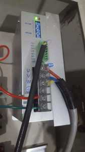
The controller is Inovance IS500P (Chinese).
IS500 Series is an AC servodrive developed by Inovance Technology Co., Ltd.
It has the following features:
※It reaches maximum power of 7.5kW and grades the power into 16 levels.
※It has five external dimensions and specifications.
※It supports the MOBUS, CANlink and CANopen communication protocols, adopting RS232/RS485/CAN communication port.
※It can implement multi-drive networking with a host controller.
See: http://www.inovance.cn/UFile/201610191513041361.pdf
Page 508 shows the comm methods. Modbus via RS-232 & 485 or the Can protocol. NOTE: The 232 and 485 are not TTL (digital) signals, so you will need a converter or adaptor to get the TTL in and out of the Ardunio. They make 485 and Can modules for the Duino world. I would recommend RS485, and the modbus route. There is some Modbos code I think for the arduino out and about.
Firstly, my model is IS500 which has two 8-pin round connectors (instead of RJ45) for CN3 and CN4.
Yes, RS485 communication module compatible to Arduinos are available. But I can't find code for MODBUS/RS485 - servo motor which could give me some idea how to control the steps of the servo motor. If you have, please share the link.
I never could get the doc's for the is500 to load :(.
With Modbus, you are reading and writing to registers on the device. These registers should correspond to a function you can set or see on the drive interface manually. The manual should give a list of those functions that can be used.
There should be a communications section showing how to write and read them to the drive. I would do some test code to read values first to get the hang of the mod interface. You may have to generate a CRC code for the data sent to the device. The manual should tell you.
Did you just get this drive or was it on another machine? If it was, then you may be able to talk to the PLC E&I person for a list of registers.
Here is the manual for IS500. The MODBUS communication section starts at page 192.
The drive was installed in old, custom designed machine. And I don't have the whereabouts of the PLC E&I guy.
The list of registers and new terms are scaring me at the moment but, I am confident once the concept is clear I could handle them easily. I would appreciate your guidance in this respect.
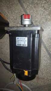
I opted to try this 3-phase stepper.
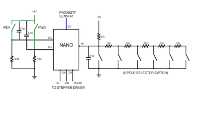
Below is the schematic of the simple Stepper Controlling Module built around Arduino Nano.
a) A 6-pole selector switch is connected to analog pin A0. Depending upon the values of the active resistors the analog value is selected at pin A0. This value is interpreted as number of STEPS to move the stepper motor.
b) D6 & D8 issue direction & pulse signals to the stepper driver.
c) D2 is connected to the output of an inductive proximity sensor thru an opto coupler. When the sensor gets on, an ISR function is called to rotate the stepper. This function is a simple for() loop which is repeated for the number of STEPS interpreted by the selector switch. The sensor is installed on the power press.
d) Two push buttons are attached to D2 and D4. FWD button moves 1 step in forward (anti clockwise) direction. REV button moves 1 step in reverse (clockwise) direction. Both the buttons are also installed on the power press (green wires).
The module is working fine as programmed. However, I have noticed that the press operation interferes the module operation, though both are totally isolated. The press is operating at 3-phase 400VAC whereas, the module is powered from a separate 220VAC. (Of course, Arduino is powered with regulated 5V). Whenever the pedal switch of the power press is pressed, the OUTPUT of the proximity sensor gets ON for a short moment which triggers the rotation of the stepper. The LED on the sensor remains off, which shows that the sensor does not gets ON, only its output is getting some "noise". Similarly, when the pedal is released, the output of the sensor gets ON again.
Is this because of the EMI? I have enclosed the controller module, 24V SMPS and the Stepper Driver inside a metallic cabinet.


