That is so kind of you, helping me out that way! Thanks a lot.
It would be just sharing my learning experience with the components and I may turn out to be of no help at all!
Good old China. Once we made our own electronics, even here in Australia, now we have outsourced the manufacturing to China with its cheap labour.
At this stage I have had no experience with using WiFi and the RPi or Arduino.
I use the Arduino Mega as it has plenty of i/o pins. It is not an overkill as a robot controller.
I meant that the Mega is overkill for only translating the signals between the Pi and the RX/TX. The Mega actually has some advantages over the Pi when it comes to controlling servo's and motors.
China certainly has a lot to offer in that regard. Would be so much better for the climate to have as much products made in all countries themselves rather then transporting all around the globe.
Greetings Josse
Still working on getting my transmitter to work and trying to get my boats engine's controlled with RPi.
Hi guys,
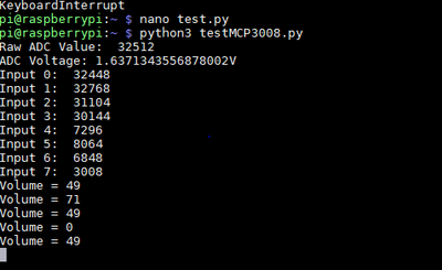
Today I started testing a little more with reading more inputs, expanding the script I used earlier. That resulted in my first modification without any alarms about mistakes or unknown commands etc.! See below my code, all I did was add readout's for all the different channels. It doesn't keep reading all the channels though, that will be my next step. I couldn't make enough sense of the remaining code to figure out how I can keep reading all 8 channels, can you folks help me out there?
import os
import time
import busio
import digitalio
import board
import adafruit_mcp3xxx.mcp3008 as MCP
from adafruit_mcp3xxx.analog_in import AnalogIn
# create the spi bus
spi = busio.SPI(clock=board.SCK, MISO=board.MISO, MOSI=board.MOSI)
# create the cs (chip select)
cs = digitalio.DigitalInOut(board.D22)
# create the mcp object
mcp = MCP.MCP3008(spi, cs)
# create an analog input channel on pin 0
chan0 = AnalogIn(mcp, MCP.P0)
chan1 = AnalogIn(mcp, MCP.P1)
chan2 = AnalogIn(mcp, MCP.P2)
chan3 = AnalogIn(mcp, MCP.P3)
chan4 = AnalogIn(mcp, MCP.P4)
chan5 = AnalogIn(mcp, MCP.P5)
chan6 = AnalogIn(mcp, MCP.P6)
chan7 = AnalogIn(mcp, MCP.P7)
print('Raw ADC Value: ', chan0.value)
print('ADC Voltage: ' + str(chan0.voltage) + 'V')
print('Input 0: ', chan0.value)
print('Input 1: ', chan1.value)
print('Input 2: ', chan2.value)
print('Input 3: ', chan3.value)
print('Input 4: ', chan4.value)
print('Input 5: ', chan5.value)
print('Input 6: ', chan6.value)
print('Input 7: ', chan7.value)
last_read = 0 # this keeps track of the last potentiometer value
tolerance = 250 # to keep from being jittery we'll only change
# volume when the pot has moved a significant amount
# on a 16-bit ADC
def remap_range(value, left_min, left_max, right_min, right_max):
# this remaps a value from original (left) range to new (right) range
# Figure out how 'wide' each range is
left_span = left_max - left_min
right_span = right_max - right_min
# Convert the left range into a 0-1 range (int)
valueScaled = int(value - left_min) / int(left_span)
# Convert the 0-1 range into a value in the right range.
return int(right_min + (valueScaled * right_span))
while True:
# we'll assume that the pot didn't move
trim_pot_changed = False
# read the analog pin
trim_pot = chan0.value
# how much has it changed since the last read?
pot_adjust = abs(trim_pot - last_read)
if pot_adjust > tolerance:
trim_pot_changed = True
if trim_pot_changed:
# convert 16bit adc0 (0-65535) trim pot read into 0-100 volume level
set_volume = remap_range(trim_pot, 0, 65535, 0, 100)
# set OS volume playback volume
print('Volume = {volume}' .format(volume = set_volume))
set_vol_cmd = 'sudo amixer cset numid=1 -- {volume} > /dev/null' \
.format(volume = set_volume)
os.system(set_vol_cmd)
# save the potentiometer reading for the next loop
last_read = trim_pot
# hang out and do nothing for a half second
time.sleep(0.5)
Still working on getting my transmitter to work and trying to get my boats engine's controlled with RPi.
Still working on getting my transmitter to work and trying to get my boats engine's controlled with RPi.
Hi folks,
It's been a while. I have tested the software from my last post, and it works. Though it doesn't yet keep reading all inputs. My father is now trying to find a way to improve the programming by making a matrix of it all, but he hasn't yet managed to get a complete working program yet.
Meanwhile I have ordered and received a new Pi 4 with 2GB and got that installed. Now I need to find some time to start testing, especially with the PWM module. I still need to connect the battery pack to the side connections. Does anyone have any reference on the range of the build-in WiFi of the Pi 4? If the range would be like at least say 150m it could well be a good way to connect between the transmitter and the boat, also because I need WiFi anyways for sending the video feeds back to the transmitter.
In the mean time I'm now thinking about how to get the propulsion modified for my use, with steppermotors for steering and with the electric motors installed vertical rather then horizontal.
Software wise, the next step will be to send the input values to the PWM module, first using only 1 Pi, and later with a wireless connection. Can you guys give any thoughts on how I can make the Pi send the values? I don't no the command for that yet.
The step after that will be controlling the stepper motor. They already have an H-bridge controller attach to it, but that will need commands too.
Thanks for the help.
Greetings Josse
Still working on getting my transmitter to work and trying to get my boats engine's controlled with RPi.
Have you thought about using the nRF24L01+ modules for remote control versus just the embedded WiFi? You would have much better range with these modules. I am assuming since we are talking about controlling a model ship that our "playing" surface is a lake or a small pond of water. In other words no buildings or terrain to interfere with our control signals.
Just a thought and an alternate solution to put some more tools in your toolkit. 😀
SteveG
Thanks for thoughts! I actually intended to use the NRF, I was only trying to find out if WiFi could be an alternative, since the NRF can't handle video I think. Due to the 7" touchscreen resolution the feed doesn't need HD resolution, which will give greater range then HD quality.
Greetings Josse
Still working on getting my transmitter to work and trying to get my boats engine's controlled with RPi.
Hello guys,
It's been quite a while now, I've been working on moving my hobby from the shed to the 2nd floor where I made a new room for it and for my home office. I did get quite a bit further with programming in the mean time and managed to get the PWM modules working and I've been working on a start for the final program for the boat. That includes now the calling of all 4 PWM modules with their unique I2C adresses programmed in. I have an Excel sheet as a guideline for the commands and the adresses which makes it a lot easier to keep going.
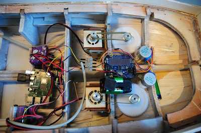
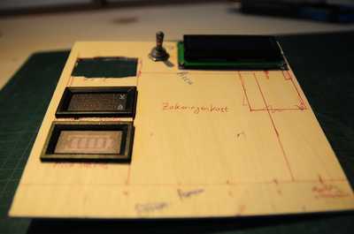
From now on I'll be working on linking the commands defined in the Excel sheet to the correct adress in the final program (let's call it wellenhancer.py) so that I'm now getting closer and closer to a working ship. Since I also got the thrusters attached and ready to go with an I2C controlled stepper motor controller hooked up to the stepper motors (see photo below). Due to some trouble in the Adafruit Circuitpython libraries I haven't got the stepper motor controller working yet though. I also started working on making a new power distribution since what I had didn't give any power anymore, even though the battery is full. See second picture below for the new power distribution plate. The rectangle hole will be used for the stepper motor and servo motors for the crane on top of the dive area where the power distribution will be located. The switch will turn on all systems in the boat.
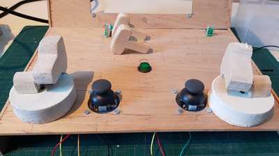
Last week I found my old home made joysticks still half finished. Thinking this option through I decided that moving a joystick to the desired angle is far more intuitive then a speed control with which holding the joystick sideways will mean that the thruster will keep turning, changing the turning circle in the process and eventually even changing from ahead to astern when moving past the 90 degree angles. So I now decided to opt for the rotating, homemade joysticks, and in the process also decided to use the same homemade throttle sticks for controlling the bowthrusters as well. See picture below:
Have you guys some good ideas for how to read the rotation of the joystick accurately (the thrusters can be moved at 0,2 degrees per step from the stepper motor)? I do have 10 turn pots which I bought specially for these joysticks but I'm trying to find out if there are unlimited rotation options which are not to difficult to make (I found a light bridge sensor but that would mean that I need to make something to have every 0,3mm some opbject to pass through the light bridge, which is to accurate to my liking to make myself). What is your suggestion?
Still working on getting my transmitter to work and trying to get my boats engine's controlled with RPi.


