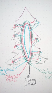
I have a fibre optic xmas tree, which i've taken apart to change.
The programmed?( all 10 follow the same cycle although there is no board, they are small clear, and have 2 small wires) which were too bright and flash to often.
Ill be replacing with 10 ordinary RGBs.
So far I worked out that each of the 3 colour PINs need a 1k resistor to control the brightness.
How to wire
Sorry I couldn't enlarge them.
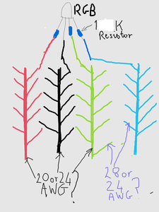
Four trunks Red, Black, Green, Blue of 20or24 AWG? going the length of the tree, with splices of 24or28 AWG? going to the RGB PINs.
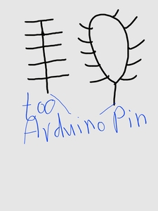
Q1 Should I make each trunk a loop, that runs up then down the tree, the RGB wires branching at each fibre optic tree branch. with a T junction at the bottom just before it plugs into the Arduino pins?
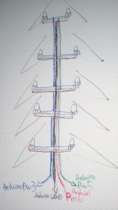
Q2 or is a single trunk wire, with staggered, Y/T junctions going to the left, then right, left then right..Or would a cross + junction at each pair of RGB's, tree branch positions. The low end of the wire going directly to the Arduino Pin, and the high end going to the last upper single or pared RGBs?
Q4 Would the ground wire be OK with the same set up as the colour RGB pin wires?
Q5 Which wires are best for the trunks 18, 20, or 24 AWG they're the ones I have, I've assumed stranded for flexibility. For the splices 24 or 28 AWG?
Tried testing ideas on tinkercad but it doesn't seem to allow connecting wires to each other.
Thank you for any help you all maybe able to give.
No such thing as too much energy, it's just un-utilised potential.
I have a fibre optic xmas tree, which i've taken apart to change.
I never even knew that there was such a thing, but Xmas trees are not my specialty!
So, if I understand correctly, you are trying to drive 10 RGB LEDs with an Arduino? Are you using an Arduino Mega2560 to drive each LED individually, or are you just using three outputs (Red, Green & Blue) to drive all 10 simultaneously.? If it is the latter then how are you supplying the current, are you using MOSFETs or BJTs?
I'm also assuming that you are using a 12 or 24-volt power supply for the LEDs, given the 1k dropping resistor?
Let me know if I have this right or if I'm confused!
As for the wire gauge, it would really depend upon how long these wires are. Obviously, the lower gauge (heavier) wire is a good choice, but it could be awkward to work with. You might consider using the 18AWG wire for the common ground connections and a lighter gauge for the LED connection.
😎
Bill
"Never trust a computer you can’t throw out a window." — Steve Wozniak
Thank you for quick reply.
MOSFETs or BJT no idea what these are.
Yes 3 pins driving the 10 RGBs, Powering and controlling probably via a nano, didgiATtiny85 board if I can, pins 6 for red, 5 for green, 3 for blue, black for ground.
Do the resistors add-up across the circuit?
I'm still messing with it, but this is the code I've been using, which worked on a breadboard with 10 RGBs and about 12x 1k resistors, but I had 4 sets of RGBs, with 3 RGB's directly behind each other. and havent yet figured out how to test the setup, on a bread board due to space.
/*
Updated Fade RGB LED Smoothly through 7 colours
Fades an RGB LED using PWM smoothly through 7 different colours pausing for 1 seconds on each colour.
Re-writted code to non blocking program using timers.
Connect an common Cathode RGB LED with appropriate resistors on each anode to your Arduino Uno;
Red to pin 6, Green to pin 5, Blue to pin 3, Cathode to GND.
Developed for Arduino Uno by Joshua David - TechHelpBlog.com
Please Feel Free to adapt and use this code in your projects.
Contact me at techhelpblog.com and let me know how you've used it!
iwouldlike to have RED ORANGE YELLO GREEN CYAN BLUE PURPLE PINK
*/
#define GRN_PIN 5
#define RED_PIN 6
#define BLU_PIN 3
byte RED, GREEN, BLUE;
byte RED_A = 0;
byte GREEN_A = 0;
byte BLUE_A = 0;
int led_delay = 0;
byte colour_count = 1; //Count the colours out
#define colour_count_max 7 //Set this to the max number of colours defined
#define colour_delay 4000 //Define the delay between changing colours in ms
#define time_at_colour 1000 //Time to stay on a colour in ms
//Some Time values
unsigned long TIME_LED = 0;
unsigned long TIME_COLOUR = 0;
//Define Colours here.
//Red
#define C2_R 255
#define C2_G 0
#define C2_B 0
//Orange
#define C4_R 255
#define C4_G 186
#define C4_B 0
//Yellow
#define C7_R 255
#define C7_G 250
#define C7_B 0
//White
#define C3_R 255
#define C3_G 255
#define C3_B 255
//Light Blue
#define C5_R 0
#define C5_G 168
#define C5_B 255
//Blue
#define C1_R 0
#define C1_G 0
#define C1_B 255
//Purple
#define C6_R 255
#define C6_G 0
#define C6_B 255
void setup()
{
//Assign initial values
RED = C1_R;
GREEN = C1_G;
BLUE = C1_B;
//Get the led_delay speed
led_delay = (colour_delay - time_at_colour) / 255;
analogWrite(GRN_PIN, 0);
analogWrite(RED_PIN, 0);
analogWrite(BLU_PIN, 0);
}
void loop()
{
//Rest of your program - Avoid using delay(); function!
if(millis() - TIME_LED >= led_delay){
TIME_LED = millis();
//Run the LED Function to check and adjust the values
LED();
}
if(millis() - TIME_COLOUR >= colour_delay){
TIME_COLOUR = millis();
//Run the Colour Change function
COLOUR();
}
}
void LED()
{
//Check Values and adjust "Active" Value
if(RED != RED_A){
if(RED_A > RED) RED_A = RED_A - 1;
if(RED_A < RED) RED_A++;
}
if(GREEN != GREEN_A){
if(GREEN_A > GREEN) GREEN_A = GREEN_A - 1;
if(GREEN_A < GREEN) GREEN_A++;
}
if(BLUE != BLUE_A){
if(BLUE_A > BLUE) BLUE_A = BLUE_A - 1;
if(BLUE_A < BLUE) BLUE_A++;
}
//Assign modified values to the pwm outputs for each colour led
analogWrite(RED_PIN, RED_A);
analogWrite(GRN_PIN, GREEN_A);
analogWrite(BLU_PIN, BLUE_A);
}
void COLOUR()
{
//Increment the colour by one or go back to 1 if maxed out
if(colour_count < colour_count_max) colour_count++;
else colour_count = 1;
if(colour_count == 1){
RED = C2_R;
GREEN = C2_G;
BLUE = C2_B;
} else if(colour_count == 2){
RED = C4_R;
GREEN = C4_G;
BLUE = C4_B;
} else if(colour_count == 3){
RED = C7_R;
GREEN = C7_G;
BLUE = C7_B;
} else if(colour_count == 4){
RED = C3_R;
GREEN = C3_G;
BLUE = C3_B;
} else if(colour_count == 5){
RED = C5_R;
GREEN = C5_G;
BLUE = C5_B;
} else if(colour_count == 6){
RED = C1_R;
GREEN = C1_G;
BLUE = C1_B;
} else if(colour_count == 7){
RED = C6_R;
GREEN = C6_G;
BLUE = C6_B;
}
}
I may try to think some more on how to test on breadboard, I can see how it looks in my head on the tree, but can't seem to work out how to transfer it to a breadboard, for testing.
No such thing as too much energy, it's just un-utilised potential.
@squish wrote:
MOSFETs or BJT no idea what these are.
https://www.makeuseof.com/tag/connect-led-light-strips-arduino/
MOSFETs or BJT no idea what these are.
10 LEDs will likely exceed the maximum current that you can obtain from an Arduino I/O pin, so you're best to use a MOSFET or BJT on each I/O line to drive them. Otherwise, you could end up burning out the Arduino.
A MOSFET or BJT will also allow you to use voltages other than 5-volts to drive the LEDs.
Here is a video I made about the subject:
😎
Bill
"Never trust a computer you can’t throw out a window." — Steve Wozniak
@robotbuilder thanks,
I'm not sure I need the MOSFETS or BJTs though?
I'm not using strips, just ordinary common cathode, RGBs. 10, 2 x 5 on either side of the tree trunk, where they have fibre optic branches glued and wrapped to the head of the RGB..
I havent needed them with breadboard testing, although I havent figured out how to breadboard test all 10 yet.
The coding format shall be very useful thatnk you.
No such thing as too much energy, it's just un-utilised potential.
No such thing as too much energy, it's just un-utilised potential.
Perhaps this helps explain it?
In reality the RGB's will be taped to the trunk of the tree, where the fibre optic branches start.
I don't need the 1k resistor for anything other than brightness, there is another script which controls for brightness. I haven't tested different resistors with that script yet. Previously I had only used resistors to protect the RGBs/components.
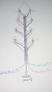
Also not sure whether to do crossroads junction as in the diagram, or staggered either side, so they are not at the same height in the trunk wires.
The other options would be to make loops for the main trunk wires, with RGB leads going up of to the left RGB 1, 2, 3, 4, 5 and then coming down on the right, RGB 6,7,8,9,10? and joining the ends together with with a spliced wire going to the arduino pins.
If I can I'll try to draw the other layouts that I'm thinking of.
Can't thank you all enough, I have much learning to do.
No such thing as too much energy, it's just un-utilised potential.
I'm not sure I need the MOSFETS or BJTs though?
The Arduino has a maximum output of 40ma per I/O port. Most RGB LEDs draw 20ma per color, although since you are using such a high value for a dropping resistor it may be less in your case. Nonetheless having 10 of these will certainly exceed the Arduinos maximum rating.
I would certainly say a few MOSFETs would be a good idea!
😎
Bill
"Never trust a computer you can’t throw out a window." — Steve Wozniak
I'll be educating myself over the next weeks or so on them, I had a quick look at the video, but it feels beyond me atm.
Before I lose them I'll put these up so I know what I meant, later.
No such thing as too much energy, it's just un-utilised potential.
Does less bright equal less milliamps ? ie if I use the script that controls for brightness would this reduce the milliamps used ?
No such thing as too much energy, it's just un-utilised potential.
Not sure what script for brightness control you are talking about but yes less current less brightness.
The analogue outputs of the Arduino are actually full voltage turned on/off so when ON it is full voltage and when OFF it is zero voltage. The brightness of the LED depends how much of the on/off cycle is on or off.
You will need a separate power supply and three transistors. Your setup is equivalent to a led strip with eight RGB LEDS. The circuit in the link I gave should work.
Clearly you just want a solved problem. However learning electronics is fun and you can design all this yourself using a bit of arithmetic and some simple formulas. You can learn the basic concepts and measurements with very simple circuits and how they relate to each other.
FORCE (volts) like water pressure
RESISTENCE (ohms) like restrictions in the pipes
CURRENT (amps) like gallons per minute
POWER (watt) like the heat or light given off
Does less bright equal less milliamps ? ie if I use the script that controls for brightness would this reduce the milliamps used ?
Putting in a higher value dropping resistor will reduce the brightness of the LED. But you have 10 of them, meaning that you could only supply a maximum of 4ma per LED. That may be too dim, they might not even light.
The most common way of changing an LED brightness is to use PWM (Pulse Width Modulation), essentially turning the LED on and off while varying the ratio between on time and off time. If you have lamp dimmers in your home that's how they work too. Controlling brightness this way will reduce the AVERAGE current draw, but it will require peak currents of 20ma per bulb (or less with your high-value dropping resistor).
And while you're wrapping your head around that there is another consideration, how are you powering the LEDs? If you have 10 RGB LEDs running at full power then each LED will consume 60ma for a total of 600ma. Mind you that is for all LEDs displaying white at the same time, but when designing a circuit it is customary to determine that maximum possible power draw and then add a healthy overhead.
You certainly don't want to draw 600ma from the 5-volt output on an Arduino! So a separate power supply is in order.
And while I'm dashing all your hopes and dreams (sorry about that!) I'll also throw in that the "40ma per I/O port" is the specification for a genuine Arduino, not a clone. Some of the Chinese clones use non-Microchip ATMega328s (the MCU that powers the Arduino) and have been observed to only source 25 or 30 ma of current on their outputs.
More blatant self-promotion:
And I apologize for complicating what you probably thought was a simple problem, however, it's probably better than building it and having it all go up in smoke!
😎
Bill
"Never trust a computer you can’t throw out a window." — Steve Wozniak
Just realised I spelled Christmas wrong in the title! oops.
Again thank you both for your advice and help, it is much appreciated.
So glad I got started now, hoping to have this up and running by 6th December.
When I started the tree, I had no idea how complicated it might be. Although I had thought my set-up could work. I wasn't sure though, so I came here to ask before getting on with the wiring loom. So glad I did! I don't mind a broken Arduino, but a burnt house, no thank you.
I enjoy learning, although my brain is not the great sponge it was, due to age and a few large dents. So it can take quite a long time and much repetition before I grasp things well enough to use. I was the kid that loved algebra!
Please don't give up on me.
Q1 Are there specific kits on amazon uk, that would have the needed items in it? I had a look and there are so many different types. Also would I need heat sinks for the MOSFETS, I want to be able to sleep at night. I have a budget of £50ish, preferring high quality over quantity. Would I benefit from getting some of the Mosfet boards used in workshop drone Mosfet video?
While I'm watching the video's and learning which way is up. I'ld like to be working on the harness, which along with taping it to the tree, will be the most time consuming process(with the exception of learning).......
Q2 .....that being the case, do you have an idea to which wiring loom/harness would be best.
I have Dupont connectors and crimper, and can solder.
Q3 Where/who are the best UK electronics suppliers that deliver, or the best sources that deliver to the UK? so far I've just used amazon uk?
Off to school now..,
No such thing as too much energy, it's just un-utilised potential.

