Can someone please tell me why I'm getting this error when I try to upload this sketch? Before I added these lines, it uploaded without a problem?
Serial.print("High");
Serial.println(switchState0);
Here's the piece of the code:
void setup() { Serial.begin(9600); Serial.println("PCA9685_MyTurnouts"); pwm.begin(); pwm.setPWMFreq(60); delay(30); pinMode(switchPin0, INPUT_PULLUP); // I'll need switchPin0 to 4 for 5 servos or 0 to 15 for 16 servos pinMode(switchPin1, INPUT_PULLUP); pinMode(switchPin2, INPUT_PULLUP); pinMode(switchPin3, INPUT_PULLUP); pinMode(switchPin4, INPUT_PULLUP); } void loop() { /////////// switchState0 = digitalRead(switchPin0); if (switchState0 == HIGH) { //for (int counter=285; counter <=370; counter++) //{ // pwm.setPWM(0, 0, counter); //swing servo left //delay(10); //} pwm.setPWM(0, 0, 370); //swing servo left Serial.print("High"); Serial.println(switchState0); //digitalWrite(ledPin0T, LOW); //digitalWrite(ledPin0C, HIGH); } else { //for (int counter=370; counter >=285; counter--) //{ //pwm.setPWM(0, 0, counter);//swing servo right //delay(10); //} pwm.setPWM(0, 0, 290); //swing servo right //digitalWrite(ledPin0C, LOW); //digitalWrite(ledPin0T, HIGH); }
The For loop above is one of my attempts to get the servo to swing slowly rather than jump from left to right (or vice versa).
And here's the error:
Sketch uses 5774 bytes (17%) of program storage space. Maximum is 32256 bytes.
Global variables use 431 bytes (21%) of dynamic memory, leaving 1617 bytes for local variables. Maximum is 2048 bytes.
C:\Program Files (x86)\Arduino\hardware\tools\avr/bin/avrdude -CC:\Program Files (x86)\Arduino\hardware\tools\avr/etc/avrdude.conf -v -patmega328p -carduino -PCOM3 -b115200 -D -Uflash:w:C:\Users\david.000\AppData\Local\Temp\arduino_build_262372/pca9685_MyTurnouts.ino.hex:i
avrdude: Version 6.3-20190619
Copyright (c) 2000-2005 Brian Dean, http://www.bdmicro.com/
Copyright (c) 2007-2014 Joerg Wunsch
System wide configuration file is "C:\Program Files (x86)\Arduino\hardware\tools\avr/etc/avrdude.conf"
Using Port : COM3
Using Programmer : arduino
Overriding Baud Rate : 115200
avrdude: stk500_getsync() attempt 1 of 10: not in sync: resp=0x00
avrdude: stk500_getsync() attempt 2 of 10: not in sync: resp=0x00
avrdude: stk500_getsync() attempt 3 of 10: not in sync: resp=0x00
avrdude: stk500_getsync() attempt 4 of 10: not in sync: resp=0x00
avrdude: stk500_getsync() attempt 5 of 10: not in sync: resp=0x00
avrdude: stk500_getsync() attempt 6 of 10: not in sync: resp=0x00
avrdude: stk500_getsync() attempt 7 of 10: not in sync: resp=0x00
avrdude: stk500_getsync() attempt 8 of 10: not in sync: resp=0x00
avrdude: stk500_getsync() attempt 9 of 10: not in sync: resp=0x00
avrdude: stk500_getsync() attempt 10 of 10: not in sync: resp=0x00
avrdude done. Thank you.
David
Sketch uses 5774 bytes (17%) of program storage space. Maximum is 32256 bytes.
Global variables use 431 bytes (21%) of dynamic memory, leaving 1617 bytes for local variables. Maximum is 2048 bytes.
The sketch seems to compile ok, but :
Using Port : COM3
Using Programmer : arduino
Overriding Baud Rate : 115200
avrdude: stk500_getsync() attempt 1 of 10: not in sync: resp=0x00
avrdude: stk500_getsync() attempt 2 of 10: not in sync: resp=0x00
avrdude: stk500_getsync() attempt 3 of 10: not in sync: resp=0x00
avrdude: stk500_getsync() attempt 4 of 10: not in sync: resp=0x00
avrdude: stk500_getsync() attempt 5 of 10: not in sync: resp=0x00
avrdude: stk500_getsync() attempt 6 of 10: not in sync: resp=0x00
avrdude: stk500_getsync() attempt 7 of 10: not in sync: resp=0x00
avrdude: stk500_getsync() attempt 8 of 10: not in sync: resp=0x00
avrdude: stk500_getsync() attempt 9 of 10: not in sync: resp=0x00
avrdude: stk500_getsync() attempt 10 of 10: not in sync: resp=0x00
the upload has an issue.
Can you try another USB cable and/or another USB port on your PC ?
Eric
Thanks Eric. I've gone back to basics and using the same Arduino, the same USB cable and the same port, another sketch loads ok. The is a very simple sketch to centre a servo. The error only happens when I include Serial.print in my sketch and the only reason for doing that was to determine that a particular pin was HIGH or LOW. And here's me thinking I was starting to understand - lol!
/* Arduino Servo Test sketch */ #include <Servo.h> Servo servoMain; // Define our Servo void setup() { servoMain.attach(10); // servo on digital pin 10 } void loop() { //servoMain.write(45); // Turn Servo Left to 45 degrees //delay(1000); // Wait 1 second //servoMain.write(0); // Turn Servo Left to 0 degrees //delay(1000); // Wait 1 second servoMain.write(90); // Turn Servo back to center position (90 degrees) delay(10000); // Wait 10 second // servoMain.write(135); // Turn Servo Right to 135 degrees //delay(1000); // Wait 1 second servoMain.write(180); // Turn Servo Right to 180 degrees delay(1000); // Wait 1 second //servoMain.write(90); // Turn Servo back to center position (90 degrees) //delay(1000); // Wait 1 second }
David
Oh then maybe you had a program connected to your COM port while trying to upload ? (or the SerialMonitor ? )
Eric
Here's the complete sketch. In the first part of void loop, where I test for switchState0, I added Serial.print("High"); and Serial.println(switchState0);
Prior to adding these lines the sketch compiled and loaded ok.
/*************************************************** This sketch can be used to operate any number of turnouts on a Model Railroad. Code blocks can be added to accomodate any number of servos. This sketch uses only two servos for this demonstration. The pushbutton can be replaced with a SPST switch commonly used on a control panel. Three pin Bicolor LED can be used in place of two seperate LEDs in each circuit. 10K Ohm pulldown resistor used on switch 330 Ohm resistor used on LEDs. One per pair of LEDs Created 03/02/2019 by Tom Kvichak https://tomstrainsandthings.com/ Additional Arduino Projects can be found at the above web address Modified by David Orr 12/01/2020 to use SPDT togle switches instead of buttons. One pole goes to cathode of red LED and digital pin on Arduino, the other pole goes to cathode of green LED and digital pin on Arduino. The central pole goes to GND. 5v rail to anode of LEDs via 1k resistor. This way only 1 digital pin is needed for each turnout switch and LED. Movement of the turnouts is via I2C and PCA9685 using 5v, GND, SCL and SDA. ****************************************************/ #include <Wire.h> #include <Adafruit_PWMServoDriver.h> Adafruit_PWMServoDriver pwm = Adafruit_PWMServoDriver(); int switchPin0 = 2; // Can add as many switches as needed - this is the 1st, set up for loop for as many as needed int switchPin1 = 3; // int switchPin2 = 4; // int switchPin3 = 5; // int switchPin4 = 6; // //int ledPin0C = 3; // C designates Closed position of turnout - I don't think I need this //int ledPin0T = 4; // T designates Thrown position of turnout - I don't think I need this int switchState0 = 0; // - this is the 1st, set up for loop for as many as needed int switchState1 = 0; // int switchState2 = 0; // int switchState3 = 0; // int switchState4 = 0; // //int buttonPin1 = 5; - I don't think I need this yet //int ledPin1C = 6; - I don't think I need this //int ledPin1T = 7; - I don't think I need this //int buttonState1 = 0; - I don't think I need this yet void setup() { Serial.begin(9600); Serial.println("PCA9685_MyTurnouts"); pwm.begin(); pwm.setPWMFreq(60); delay(30); pinMode(switchPin0, INPUT_PULLUP); // I'll need switchPin0 to 4 for 5 servos or 0 to 15 for 16 servos pinMode(switchPin1, INPUT_PULLUP); pinMode(switchPin2, INPUT_PULLUP); pinMode(switchPin3, INPUT_PULLUP); pinMode(switchPin4, INPUT_PULLUP); } void loop() { /////////// switchState0 = digitalRead(switchPin0); if (switchState0 == HIGH) { //for (int counter=285; counter <=370; counter++) //{ // pwm.setPWM(0, 0, counter); //swing servo left //delay(10); //} pwm.setPWM(0, 0, 370); //swing servo left //Serial.print("High"); //Serial.println(switchState0); //digitalWrite(ledPin0T, LOW); //digitalWrite(ledPin0C, HIGH); } else { //for (int counter=370; counter >=285; counter--) //{ //pwm.setPWM(0, 0, counter);//swing servo right //delay(10); //} pwm.setPWM(0, 0, 290); //swing servo right //digitalWrite(ledPin0C, LOW); //digitalWrite(ledPin0T, HIGH); } ///////////////////// switchState1 = digitalRead(switchPin1); if (switchState1 == HIGH) { pwm.setPWM(1, 0, 370); //swing servo left } else { pwm.setPWM(1, 0, 285); //swing servo right } /////////////////////// switchState2 = digitalRead(switchPin2); if (switchState2 == HIGH) { pwm.setPWM(2, 0, 370); //swing servo left } else { pwm.setPWM(2, 0, 285); //swing servo right } /////////////////////// switchState3 = digitalRead(switchPin3); if (switchState3 == HIGH) { pwm.setPWM(3, 0, 370); //swing servo left } else { pwm.setPWM(3, 0, 285); //swing servo right } //////////////////////// switchState4 = digitalRead(switchPin4); if (switchState4 == HIGH) { pwm.setPWM(4, 0, 370); //swing servo left } else { pwm.setPWM(4, 0, 285); //swing servo right } }
David
No another program but possibly the serial monitor. Do you mean that the serial monitor can't be active when you upload a sketch to the board that has the serial monitor in it?
David
You're right. I've made sure the serial monitor wasn't active and removed the // to include the Serial.print lines and it up loaded! Yay! Something new I've learnt.
David
Usually the serial monitor does not "lock" the port (actually it temporarily releases it) since it is controlled from the same main process (Arduino IDE) that launches avrdude for the actual upload.
But I had sometimes the issue nevertheless (mostly when I had multiple Arduino IDEs running)
So when that happens, I close all my IDEs, disconnect the board from USB, and restart the process...
Eric
Thanks. Sorta like closing Windows and starting again. Now all I need to do is figure out how to slow the movement of the servo horn.
David
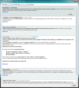
It may be overkill, but you can have a look at ServoEasing (compatible with PCA9685), or another easing library :
Eric
Thanks I'll have a look. I've been thinking along the lines of the map command which can change the angle I want to the pulse the PWM needs. I just need to figure out how to fit it into each switchState evaluation.
David
If you want to do it without other libraries, I guess the issue will be "not to block" the loop() while moving a servo (which the commented for loops in your code would do), making the script unresponsive until the servo movement is finished.
That would probably mean managing the current vs. target angle/PWM value per servo, and using the millis() function to manage timed increments/decrements, one step per loop().
Eric
I think that's what I'm thinking of but you've put it into words ? - lol
David
I don't know if this is your problem, but just a thought.
In your code, I don't see a delay of any sort (built in or otherwise), and you're calling the Serial.print statements directly after a PWM servo move operation.
As the operation may not have actually completed it's operation yet, perhaps this might also be a problem why the communications port is not ready?
Is that why there was a delay(30) there? I thought it was superfluous so removed it. But it was there when I was having the problem. It's in the void (setup).
David