Hi all. I have a power supply board that is being fed with a tested wall adapter. The voltages from the adapter are 18V and 7.5V. When I test the output on the board I get the following:
5V I get 0.9V
12V I get 26V
-5V I get 0V.
For what it’s worth all the Caps look OK. My question is where should I start my trouble shooting?
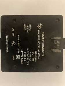
Let's start by making sure we understand what you are saying. What do you mean by 'wall adapter', do you mean a wall wart, cell phone charger, something else. Maybe post picture of it and the info plate.
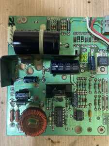
Also the power supply board, name, model, picture.
Debugging for this would be from wall out, so measure voltage coming out of the 'adapter' as step 1 and report back.
First computer 1959. Retired from my own computer company 2004.
Hardware - Expert in 1401, and 360, fairly knowledge in PC plus numerous MPU's and MCU's
Major Languages - Machine language, 360 Macro Assembler, Intel Assembler, PL/I and PL1, Pascal, Basic, C plus numerous job control and scripting languages.
Sure you can learn to be a programmer, it will take the same amount of time for me to learn to be a Doctor.
Ok. So by “wall adapter” I mean the stock power supply that came with the TI 99 4/A. It has four pins and supply’s 18V and 7.5V
I have tested it plugged into my standard North American outlet and the voltages are within 5% of what they should be. (They are slightly high).
When I plug the supply into the board which is a TI 99 4/A Linear Supply (Model 1049689-3) and check the voltage that would be going to the “motherboard” I get the above readings .
Is this enough information to help? Thanks in advance for any suggestions.
@mtlatc Ok, that's better, I assume you have googled for the PS diagrams/manuals and din't find anything so one approach would be to start at the input pins with a VOM and simply trace the power. Another would be to remove power and again with the VOM verify each resistor. Using a component tester do the same with the capacitors and the voltage regulator right side 3 leads. Also check continuity of the coil. The high voltage is what makes me suspicious that one or more components is fried. Sorry, I have no magic approach. I didn't mention the absolute first steps which are a look with a magnifier, followed by flexing the board while the meter is connected to see if any hairline cracks. Good luck.
First computer 1959. Retired from my own computer company 2004.
Hardware - Expert in 1401, and 360, fairly knowledge in PC plus numerous MPU's and MCU's
Major Languages - Machine language, 360 Macro Assembler, Intel Assembler, PL/I and PL1, Pascal, Basic, C plus numerous job control and scripting languages.
Sure you can learn to be a programmer, it will take the same amount of time for me to learn to be a Doctor.
Hi @mtlatc,
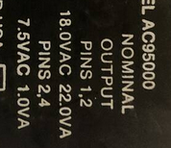
Looking at the photo you include, this power supply is 'unusual' ... its outputs are AC, not DC!
More surprisingly, there is quite of lot electronics ... I have come across a number of very simple power supply units with low voltage AC output in the past, leaving the conversion to DC etc. to be done in the main unit, but those 'power supply units', usually consist of little more than a transformer (and maybe a fuse, etc.)
ie 18 VAC and 7.5 VAC
I haven't tried to decipher the electronics, which would be needed to try to fix it, but are you looking for a general purpose power supply? .. In which case, I am wondering if you are on a wild goose chase ...
Or perhaps you are interested in vintage computer restoration ... as a quick Google suggested this device (to power a vintage TI computer,) has some interest?
Either way, was your meter switched to DC or AC?
Also, I don't know how familiar you are with working with live electronics, but if your experience is limited, remember some parts of that unit could give a very nasty shock ... possibly fatal .. so please take care.
Sorry, this is more questions than answers, but we have to start somewhere.
Best wishes, Dave
Some details on the power board,
https://challenges.robotevents.com/uploads/0017887_original.pdf
A cleaner view of the board,
Hi all. I have a power supply board that is being fed with a tested wall adapter. The voltages from the adapter are 18V and 7.5V. When I test the output on the board I get the following:
5V I get 0.9V
12V I get 26V
-5V I get 0V.
For what it’s worth all the Caps look OK. My question is where should I start my trouble shooting?
Here's a radical solution .... ditch it and buy a supply suitable for you needs. Is it worth the investment in time when, at the end of the day, you find it is faulty or it is not possible to modify?
Regards
Ron B
Ron Bentley
Creativity is an input to innovation and change is the output from innovation. Braden Kelley
A computer is a machine for constructing mappings from input to output. Michael Kirby
Through great input you get great output. RZA
Gauss is great but Euler rocks!!
I read "a common failure among TI-99/4A systems is the power supply." So that board my just be faulty.
Hi @mtlatc,
Sorry, I misunderstood your photos ... I thought you were providing two views of the power supply unit ... not two different objects, which is more obvious with the help of @robotbuilder 's contribution.
If you are trying to restore the whole calculator unit as an example of calculator/computer history, then I can understand why you might try to fix the power supply. However, if you are just want a power supply for some other project, then, as others have suggested, I would recommend buying one.
I would also be concerned that the rest of the calculator unit may have been damaged if 26V has been applied to a 12V rail, but obviously this is just speculation.
-------------------------------------------------------------------------------------
Assuming you are trying to restore the whole unit, not just the power supply ...
So the wall unit is basically a transformer, with two secondaries .... which makes more sense.
You need to trace out the circuit of the board a bit more to figure out exactly how it is supposed to work.
The extra info from @robotbuilder lists two regulators ... a -5V output 7905 device, and a low current UA723, whose voltage is set by a pot. I notice two other 'power transistor-like' parts in the centre, which could be other regulators or could be a transistors, using the UA273 as some kind of regulator/reference. (I can't see the part numbers of these devices.)
The extra info also mentions a comparator. At a guess, this might be some kind of power up sequencing circuit, in which case failure of one output may prevent the other outputs being enabled.
If I was trying to fix this myself, I would attempt to draw out the circuit, then start systematically checking the functionality of the rectifiers, smoothing capacitors, and regulators in approximately that order. The need for both a negative (-5V) and two positive rails, from what appears to be just two secondaries, suggests some kind 'clever' tweak that will probably be obvious with a schematic, but could be confusing to debug without a clear understanding of the circuit.
-----------
Good luck, Dave
@mtlatc Can you tell us if you are trying to just restore/repair the power supply or the entire old computer.
If the power supply, your time would be better spent buying a new supply. Your time is worth much more.
If you are attempting to restore the old computer, all the best, just remember there may be parts you can no longer get.
First computer 1959. Retired from my own computer company 2004.
Hardware - Expert in 1401, and 360, fairly knowledge in PC plus numerous MPU's and MCU's
Major Languages - Machine language, 360 Macro Assembler, Intel Assembler, PL/I and PL1, Pascal, Basic, C plus numerous job control and scripting languages.
Sure you can learn to be a programmer, it will take the same amount of time for me to learn to be a Doctor.
@ALL -- I guess in the future I should be more detailed. My "power supply" which is what I would call the unit that plugs directly into the wall works properly and has been tested and provides the proper voltages.
That "power supply" plugs into a "power board" that converts the 17.5 and 8V AC into 5V, 12V, and -5V DC. This "power board" then connects to the computers "motherboard"
After reading several of these post ( looking at you @DaveE) I have my 12V and -5V giving proper readings. My 5V is still only reading 0.9V so that is where I'm going to have to focus my attention.
Once I get the 5V situation rectified I will plug the whole system up and see if the computer will work. As @zander noted I do not intend on spending a lot of time or money if the system will require a lot of repair.
@mtlatc Keep in mind that although the 5V supply at 0.9V shouldn't harm much if anything, that 12V at 26V will start to fry components unless they are all fried already. If you decide to scrap the PS board, Bill made a great video about using a laptop brick at 19V to create a nice power supply, I enlarged on Bill's design to create my 3.3V, 5V, 12V, Variable small supply. Good luck.
First computer 1959. Retired from my own computer company 2004.
Hardware - Expert in 1401, and 360, fairly knowledge in PC plus numerous MPU's and MCU's
Major Languages - Machine language, 360 Macro Assembler, Intel Assembler, PL/I and PL1, Pascal, Basic, C plus numerous job control and scripting languages.
Sure you can learn to be a programmer, it will take the same amount of time for me to learn to be a Doctor.
@zander -- I used Bill's video on making the ATX power supply (3.3V, 5V and 12V) and could easily modify that to provide the -5V option and power the system.
I solved the 26V -vs- 12V issue (also the -5V issue) every test shows that I'm right at 12V and -5V so that should not be a problem.
Tonight I'm going to try and trace the 5V and see if I can find anything. If not, I may just power the "mother board" at 5V and 12V and see if it's worth my time. (As I understand the -5V is used for speech synth and I'm not concerned with that for now). Thanks for your responses.
@mtlatc I recall vaguely Bill mentioning -5V and my recollection is it had no use. I also have an ATX supply but not completed and did not use the -5V. I have no idea why speech synth would need -5V.
First computer 1959. Retired from my own computer company 2004.
Hardware - Expert in 1401, and 360, fairly knowledge in PC plus numerous MPU's and MCU's
Major Languages - Machine language, 360 Macro Assembler, Intel Assembler, PL/I and PL1, Pascal, Basic, C plus numerous job control and scripting languages.
Sure you can learn to be a programmer, it will take the same amount of time for me to learn to be a Doctor.
@mtlatc I recall vaguely Bill mentioning -5V and my recollection is it had no use. I also have an ATX supply but not completed and did not use the -5V. I have no idea why speech synth would need -5V.
@zander, and @matlatc, While reading your post, I think I can clarify why the -5V is present on the power supply board..it's probably for the audio amp. It's routinely used to power bi-polar amps .. +5V to -5V rail to rail.
OpAmps circuits use them alot...
regards,
LouisR
LouisR


