Hi, I've been interested in the Using Inexpensive 433MHz Transmit and Receive Modules with Arduino video. Thanks @dronebot-workshop for this; it has been very informative beyond just hooking up wires.
These modules seem great for a lot of uses, and I've seen some of those uses in this and other videos. A lot of people have solved their antenna issues. So I'm keeping at it.
I found that with the supplied antennas, I still get just about 2 cm reliable transmission distance, which is what Bill reported without any antennas.
I got a 3-pack of transmitter plus receiver, including 6 little springy antennas, bare copper wire by the looks of it. The coiled part is about 18 millimeters, so maybe that translates to 17.3 centimeters when fully stretched out. I don't know; maybe I'll sacrifice one and stretch it out and measure it.
I've also prepared some 17.3 cm lengths of 18 AWG solid wire to try with one xmit/rcv pair, just as shown in the DBWS video. Then it occurred to me, maybe I'm just installing the antenna wrong, or in the wrong place.
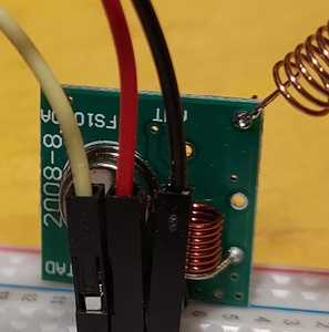
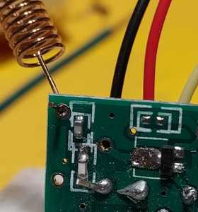
After a couple of hours on the forum, I have not found any photos of working setups. On my own transmitter modules, the silkscreen legend "ANT" appears plausibly close to three different holes, so I picked one and soldered there. I feel like a dummy, but as noted, I can't find any photos of this. I'm posting some of my setup, though with the caution for others not to follow this because of my terrible range.
That's the transmitter, front, then back.
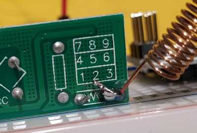
Here's the receiver, the back side. Note that this one is not a through hole, but rather a couple of leads sticking out. Those leads are fairly long, compared with many that are clipped short on commercial boards. So I figure that is where I'm supposed to solder the antenna. (I'm realizing that a couple years of learning about wired electronics shows I know nothing at all about antenna 🙂 ).
Question: there are actually TWO of those longish leads, and they have a squiggle symbol between them. Am I supposed to solder them together? Or to solder antennas to both of them, pointed in opposite directions?
Thanks to @robo-pi for providing a link to the hardware he purchased.
An interesting thing is that these 433 MHz modules come from several (many?) different manufacturers, so the silkscreen will look different. Looking at that product listing, the picture of the front of the transmitter clearly shows the label "ANT" right near the corner. So perhaps I got that position right.
Any tips, with or without photos, are greatly appreciated! In the meantime, I will keep experimenting. It's been a great experience, and by the way, other than the range issue, the software portion works great. I've tinkered with variable length messages, including an integer loop counter, so I can see how many dropouts occur at a given distance.
I will also try Bill's suggestion from the video, about attaching another, same length, antenna to the ground.
In theory, theory and practice are the same.
In practice, they're different.
I don't know if this will help you or not ...
Anything seems possible when you don't know what you're talking about.
@will Thanks, Will. Don't know how I missed that one, but I will check it out.
In theory, theory and practice are the same.
In practice, they're different.
OK, updating my earlier status. The little bare copper coils are miserable as antennas. I did stretch one out as far as I could; it was more than 20 cm.
The Antony Cartwright video did show some good shots of just where the antenna was soldered onto the transmitter; confirmed I was right. It was at the very corner.
I did solder mine likewise, at the very corner, solid core 18 AWG wire. I pointed it straight up, so at that point, matched that video and also what I learned from Bill's. I did the same for the receiver.
The result was immediately better. I still have it on the top of my bench, but much farther than I was able to manage without the straight-wire antennas. So, good news. I will test farther distances soon. Thanks for all the help.
In theory, theory and practice are the same.
In practice, they're different.
After further testing with the long, straight wire antenna, I was able to get about 25 meters range. This was through two walls, then outdoors to a spot on the trellis, in the shade, where I'd like to put a temperature and humidity sensor. There were plenty of periods of continuous coverage, i.e., I looked at the loop counter generated at the transmitter end once per second, and there were no dropouts. There were also times when I wouldn't get a transmission for 3 to 8 seconds, but I can live with that. I mean, the temperature changes, but not that fast. If I can also incorporate the low power library, the processor will spend most of its time asleep anyway.
As a side note, my setup that works includes wires I cut long, on purpose, since it's easier to do that, solder it, and then cut to length. What I found was that the 20 cm receiver works, and the 17 cm one does not. Is it possible that the 433 MHz rating of the transmitters/receivers is off a little, and therefore the wavelength is off a little too? Or not. It's also possible that I made bad solder joints on one unit, or that of the lot of 3 I purchased, one is just bad. Moving on 🙂
In theory, theory and practice are the same.
In practice, they're different.


