Hello! I have followed DBWS for several years and have done several of the experiments related to power supplies, FTDI programming of Arduino-like microcontrollers, including ESP32-CAM, DC motors, motor controllers, etc. This is all cool. Now I want to implement one of the projects, and I'm finding a project quite a step up from an experiment.
Specifically, I'm struggling with the ESP32-CAM Robot Car.
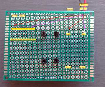
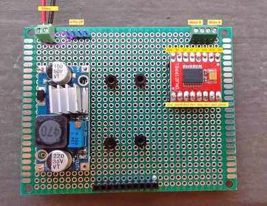
I've sourced my components, and laid them out. I'm trying to follow Bill's article as closely as possible, so this is my Main Board (see photos). On the front, I've got the motor controller in female sockets. On the back, though, notice I haven't added any wires.
So, how can you possibly manage making all those connections correctly? Do you just memorize the pinouts of ESP32 and TB6612FNG?
I took these photos, to try to give myself a guide. I added the little labels, the red with yellow background, to try to keep track of all this.
Does anyone else do this? If not, what do you do to help your process?
Thank you,
John
In theory, theory and practice are the same.
In practice, they're different.
@jbo Hi John,
Generally, I agree with the above comment, except perhaps there might be other solutions in some cases, most of which require more upfront work but may pay off in the long run with more complex situations. Every different job has different challenges, and sometimes different answers.
In this case, I sense (maybe incorrectly), you are familiar with the general task, but are worried about the number of wires, complexity and perhaps, lack of familiarity of those components, etc. I have a couple of suggestions, for you to consider.
As one who remembers occasionally using printed maps, I was not adverse to rotating it to try to avoid getting left and right mixed up. Similarly when approaching a wiring job, except of course, there can be two sides to cope with as well. Hence:
Make a sketch (map) of each side of the board, showing the numbered pins, and a reference to the component. This is to try to prevent mistakes of counting the pins from the wrong end or side. Also, add some landmarks to the board using pen or sticky labels or ??, and mark those on your sketches. This is also particularly useful when there is a long row of pins ... counting 3 from right end is easy, counting 3 from the wrong end is also easy, miscounting 23 from either end is even easier. 🙄 Similarly, 'landmarks' are useful if you connecting to a device on the opposite side of the board.
If there are a 'lot' of wires (where 'lot' is a personal judgement), you could decide to do a connnection list. That is systematically make a list of all of the connections in a From 'Chip1 Pin 3' To 'Chip3 Pin5' style. A simple spreadsheet table might be handy.
Some people may recognise this as a 'Net List', which used to be the way of converting a schematic into a list of connections for PCB layout, as well as input for SPICE, etc. and if you have the schematic on your PC, it might be possible to at least partially create it automatically.
Otherwise, if you have a paper copy of the schematic, the 'old skool' way is to colour each connection in on the schematic as you list it, and add a connection reference to both the schematic and the list, so they are easy to tie up. Also, if you are using different wire colours, thicknesses, etc. add this information into the list and maybe the schamatic.
Then as you wire, maybe add a sticky reference label to each wire. And of course, tick off the connection in your table.
As I started, these are only suggestions .. if you have 5 wires to add, they are totally over the top, if you have 5 thousand connections, they would be an absolute minimum. Your project is probably between 5 and 5000, so it is your call.
Good luck and I hope it works first power on!! Dave
The connection list that Dave mentions is a method that used to be used, and may still be used, when one was doing connections using wire wrap. I still have a control board for two 16KB memory boards I wire wrapped on a S-100 sized board for an Altair computer. I might even have that connection list around here as well. And if I'd had access to a spreadsheet back in the late 70's it would have been a lot easier. Then all we had was pencil and paper. 🤣 😎
SteveG
@codecage OK, thanks for that confirmation. I am sort of making some of it up as I go, but knowing others are in the same boat helps. -- John
In theory, theory and practice are the same.
In practice, they're different.
@davee Dave, thank you for your remarks and suggestions.
. . . you are familiar with the general task, but are worried about the number of wires, complexity . . .
Yes! This does accurately describe where I'm coming from. I have done several experiments successfully, then attempted Build a Robot Car with Speed Sensors. I got the motors running, the opto-interrupter speed sensors, and an Arduino Nano. So, all the intermediate sketches were fine, but the final product did not run. I chalk it up to learning, which is fine. I think I made a wiring error somewhere, which is why I'm skittish.
Also, add some landmarks to the board using pen or sticky labels or . . .
Hmm, this sounds good. I had noted "natural landmarks" on the Main Board such as the 4-pin connector going to Top, 2-screw terminals to battery, and so on. But it wouldn't hurt to make them explicit. From the article, I'm always thinking of one side of the motor control as the "logic side" versus the other "power side," so I think that's a good place for a label.
I do have a spreadsheet where I replicated the connections shown in the video for this project, a little From - To table listing, for example, every connection from the ESP32 to the Motor Controller. But with your comment, I'm thinking of taking that one step further, listing the connections from the ESP32 to the bent pins male connector on that board, then the pins on the socket on the Main Board, and then to the Motor Controller. Not sure how much detail will help, but I do know I originally thought of this as one big breadboard, watching the video. Actually wiring it, across three boards, is another step for me. However, I hasten to add that I'm very much in favor of the three boards; they're modular, and at least theoretically some parts of their functions can be tested separately. This definitely appeals to my software background 🙂 - I would test any three lines of code if I could, and if I thought it might flush out any errors.
I am using different gauges of wire. I'm still just getting used to it, so 18 AWG (solid core) and 30 AWG are both giving me some trouble, though for different reasons. I just got some 22 gauge stranded, and am hoping I can learn to work with it. And yes, the color coding helps a lot. Thanks again for your suggestions. - John
In theory, theory and practice are the same.
In practice, they're different.
I still have a control board for two 16KB memory boards I wire wrapped on a S-100 sized board for an Altair computer.
Whoa! I was in awe of those with the serious skills to actually do this. A programmer's role is to say "that's a hardware problem," but I was secretly envious. Years later, with IoT and such, it's my turn to dabble in actually putting things together and getting them to work.
Then all we had was pencil and paper.
😥 😪 Quit complaining. Of course you had a pencil. How else were you supposed to calculate fifth roots? Or interpolate your logarithms?
Thanks. --John
In theory, theory and practice are the same.
In practice, they're different.
Hi John @jbo,
According to Wikipedia, the Altair came out in 1974 .. the year I bought a CBM scientific calculator that included roots, logs, trig and brackets ... whilst the Hewlett Packard with its novel Reverse Polish Notation and similar practical capability to the CBM (provided you could do Polish backwards) preceded it by at least a couple of years and cost about 8 times as much as my CBM .. so I probably wouldn't have used a pencil and paper for logs or fifth roots at that time .. on the other hand neither calculator would much good at spreadsheets or wiring lists .. And it wasn't until 1982 that I played with S-100 computer, though I had played with other microcomputers before that ... Those were the days? 😀
More seriously, John, I am pleased to hear you appreciated my comments and I hope you found them helpful - as I said, they were only suggestions to adopt or ignore as best fits your particular situation. Your next project may be different! Best wishes, Dave


