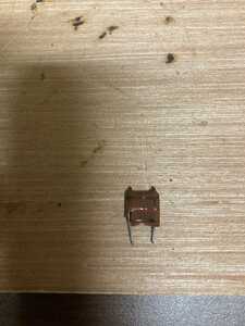
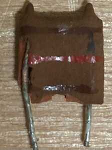
The pictured is listed as an Oscillator 2-4.5uH in my BOM. Does anyone know a modern replacement because Google has not been my friend.
The picture appears to be of a coil. Can you use a magnifying glass to see if it has any part numbers?
2-4.5uH sounds like 'micro Henry's' which is how coils are classified. An oscillator will have one of those but also has other parts.
Search using something like this '4.5 micro henry coil' which returns over 3 million results.
A big supplier is mouser and here is the page google found for that search
https://www.mouser.ca/c/passive-components/inductors-chokes-coils/?inductance=1%20mH
First computer 1959. Retired from my own computer company 2004.
Hardware - Expert in 1401, and 360, fairly knowledge in PC plus numerous MPU's and MCU's
Major Languages - Machine language, 360 Macro Assembler, Intel Assembler, PL/I and PL1, Pascal, Basic, C plus numerous job control and scripting languages.
Sure you can learn to be a programmer, it will take the same amount of time for me to learn to be a Doctor.
The pictured is listed as an Oscillator 2-4.5uH in my BOM. Does anyone know a modern replacement because Google has not been my friend.
The picture appears to be of a coil. Can you use a magnifying glass to see if it has any part numbers?
2-4.5uH sounds like 'micro Henry's' which is how coils are classified. An oscillator will have one of those but also has other parts.
Search using something like this '4.5 micro henry coil' which returns over 3 million results.
A big supplier is mouser and here is the page google found for that search
https://www.mouser.ca/c/passive-components/inductors-chokes-coils/?inductance=1%20mH
It has a brown stripe on the top, and red stripe on the middle, and another brown stripe on the bottom.
But that is all. I can find anything online that resembles this.
@mtlatc That looks like a 120 ohm resistor, can you measure it with your meter?
First computer 1959. Retired from my own computer company 2004.
Hardware - Expert in 1401, and 360, fairly knowledge in PC plus numerous MPU's and MCU's
Major Languages - Machine language, 360 Macro Assembler, Intel Assembler, PL/I and PL1, Pascal, Basic, C plus numerous job control and scripting languages.
Sure you can learn to be a programmer, it will take the same amount of time for me to learn to be a Doctor.
Hi @mtlatc,
That is a weird looking part. I think Ron @zander has covered most of what can be gleaned from a photo, and as he says, coils are specified in microHenries. Small inductors are readily available (ignoring the troubles of the present component drought), but I am not persuaded that is or is not an inductor. Colour coding can apply to lots of different types of components ... prior to laser engraving, it was an easy way to mark up small parts.
I am not sure of the age of the part .. is it from your TI99/4 revival? If so, I don't think it would be resistor, as it would have been so much simpler to use an off the shelf part, and they don't usually look like that.
I think you may need to look deeper ... and provide more clues. What do you think that part of the circuit was achieving? Trace out the circuit, etc.
Are there any other similar parts, in better condition?
Good luck, Dave
The two pips on the top suggest a joint between fine coiled wire and connection wires.
@davee @hilldweller From everything I’ve learned it is a adjustable coil with a protective coating to ensure it is not accidentally adjusted…. It is connected to a10.73 mHz crystal and is supposedly used to fine tune that crystal. I’m pretty sure I won’t find another one like it. It’s adjustable between 2.5 and 4 micro Henry’s.
@davee @hilldweller It’s adjustable between 2.5 and 4 micro Henry’s.
Adjustable inductors are ( or were, pre-digital ) very common. All had a hole to put in a tool to adjust them.
A phrase comes back from the distant past "pulling a crystal". It might be worth looking it up.
Hi @mtlatc,
I as I said, this is a bit of a one-off. It is actually difficult to make variable inductance that is physically small ... it is possible by having the core screw in and out of the coil, but I would expect to see a cuboid shaped metal can or a tube with a square base for the pin connections if it was not screened. The latter is what I will show you further down.
----
Much of the difficulty I have been having arises from not getting the full story of what you know, so can I start by making a plea for mmore information from anyone asking a question? This an all too often experience.
---------------------
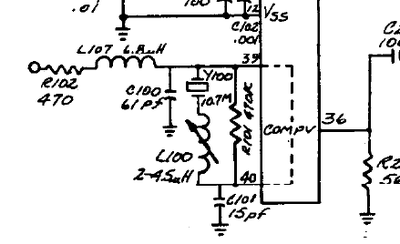
However, based on previous conversations, plus the additional gem of "10.73 mHz crystal", I have tracked down a schematic of the TI99/4 on Github, and can now see the part ... it is indeed an inductor connected to a crystal which forms an oscillator for the TMS9918.
As for finding a replacement ... I think you should be able to find something that will be electrically OK, but it will probably look rather different. Of course, you may be lucky in finding something closer, but for a starter, I did a quick Google and found:
https://www.aliexpress.com/item/32823642390.html
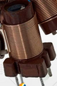
which looks like:
and claims: The inductance value core skeleton inside 3.6mm core diameter 8mm height
Adjustable Min: 2.6uH Adjustable maximum: 6.8uH constant value Without core: 2.1uH
which sounds promising. Unfortunately, you have to buy 10 of them, but even that is not huge cost.
I should say, I know nothing about this part or its supplier ... I am not recommending it, just offering it as something to consider and as an example of what to look for. Clearly, it is physically different, but it is the 'shape' I would expect for an adjustable inductor.
--------------
And in case you haven't come across ferrite cores, the little dark grey cylinder that runs down the middle of the coil. To adjust, it has a screwdriver slot, or occasionally a hex 'allen key' like slot. This must only be adjusted with a suitably shaped plastic tool ... using a metal tool will certainly affect the inductance as you adjust it, and very likely crack the ferrite, rendering it useless. Suitable tools are sold, but if it is a screwdriver slot, then a few minutes with a piece of scrap plastic, mini-hacksaw and file should provide an alternative.
Adjusting the core may affect the oscillators ability to oscillate, but I think its intention is to trim to an exact frequency (ie to within a few Hz). At a guess it is
10,738,635 Hz which is 3 x 3.579545 MHz±10 Hz ... the American NTSC colour sub carrier frequency .. https://en.wikipedia.org/wiki/NTSC
I assume you have a monitor/TV capable of showing the composite NTSC picture ... At a guess, if it is oscillating, but slightly off ( 100s of Hz) frequency, then you will get a picture but it will be monochrome or crazy colours, so I guess get it oscillating first, for which a scope may be helpful, then tweak for the best picture ... I have never had an NTSC TV, but I recall that on my side of the Atlantic which used PAL, it was often suggested to mean Never Twice the Same Colour 😜 ... (actually National Television Standards Committee), so I don't know how fussy it will be.
Hope this helps.
Best wishes,
Dave
What is a BOM?
The part looked very much like a capacitor to me. Easy to check with a multimeter. Open circuit if a capacitor (unless shorted) or some resistance if a coil.
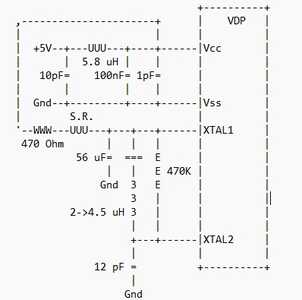
This makes reference to a 12pF by-pass capacitor, (brown,red,brown code?) in series with a 2->4.5 uH coil
https://www.unige.ch/medecine/nouspikel/ti99/tms9918a.htm
@robotbuilder A BOM is a Bill of Materials. The term is often used to indicate all of the parts required to complete a project or a particular section of the project.
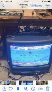
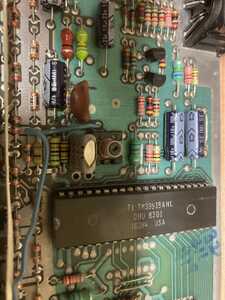
@davee Yes you are right. I need to take more time and fully explain what I’m doing. I have been told in the last few days I fail to give enough information. For that I apologize. See the photo below to get a look at the board I am working on. I have a video of the issue I’m trying to fix but it is too big to upload. You may be able to get the just with the attached screen shot
Hi @mtlatc,
Thanks for the update ... and yes a bit more information that would have been useful before 😉
The photo shows the variable inductor on the board, looking much more like a variable inductor than the flat thing you were displaying!! Presumably from the photo I included, you too can see the resemblance!
The circuit snip I included shows a 15pF capacitor, in the same position as 12pF in @robotbuilder's sketch/reference. The component you are showing is much more likely to be a capacitor. The difference between 12pf and 15pf is probably not that significant, though it might mean a small adjustment to the inductor.
You should be able to check that it is this capacitor by looking at the circuit board ... the holes for the component should connect to ground and the inductor.
Best wishes,
Dave
It seems to be a problem with the vertical oscillator?
The circuit you showed seems to correspond with the schematic I posted.
I would have to have the actual board to trace the fault 🙂
More information would have helped a lot!!
Here is your brown capacitor...
https://www.classic-computers.org.nz/blog/2014-02-22-ti99_4a-reconstituting.htm

