@huckohio @byron @briang @codecage ;for FYI another topic ; However did post in " projects corner , Help Wanted "
Taken Bill's Video "Using LCD Display with Ardui
no" a step further . Constructed the Arduino Hub project ( see attached ) Light Sequence Creator Issue: not sure I'm using the right platform - the program light_sequencer.c is C++ . I uploaded it to CODEBlock 8.02 -Platform IDE no build errors , but when I build and run ( usb to pc ) the arduino green light and one small yellow LED comes on but the R and T small lights do not . The program appears not to be communication with the Uno or my schematic ( see attached ) Can't use Arduino IDE since it accepts a file with ino. extension WHAT AM I DOING WRONG
-
Post this on the Arduino form also but no replies Did check my wiring that seems okay I allso attached a little of the program
I see you are doing an illuminating dive into electronics and programming. 😀
I fear I cannot bring too much light to bear on you project but I can say how I approach projects that I've grabbed from the net that don't appear to work at first.
And that is to break everything down into small steps. For example maybe you disconnect all your electronics except the LED's. Then you write of copy a bit of code to do something with those LED like make them flash in sequence. This will at least validate the wiring to the LED's. And then move on to do something simple with your LCD, again to validate all the connections and the programming logic, at least for simple steps.
For the code you downloaded, start by identifying small bits of the code that appear to do something you recognise and just copy that code or comment out all the other bits for now /* xxx */ and see if you can get the code snippet to run. If you are not familiar with platform IO and C++ to flash your arduino then don't forget you can copy/past the C++ code into the Arduino environment and compile it from there.
Have a nice cup of tea between the small steps helps too. 😎
@ byron
I switch out the Uno R3 I just purchased , put in my old uno broad and all the LED s came on so my circuit is okay and board communicates except for the LCD display
I tested my LCD display with a simple " Hello World " program and except for power , no data pin communication - I did solder pins in and may have damaged the display - I ordered another one with pins
There is a definite problem with the display so I'll see what happens when I put the new one in
Why the UNO R3 did not communicate - do I have to boot load it ?
Why the UNO R3 did not communicate - do I have to boot load it ?
I don't think so, R3's come ready to roll. Have you tried a simple blink test with one LED or even its on board LED if it has one? Also you could try a simple hello world program. If these pass then your new board should be OK, otherwise I suggest you return it from whence it came as DOA.
@byron Simple test UNO R3 Why did I not think of that - will do . I'll keep the old uno in place for now
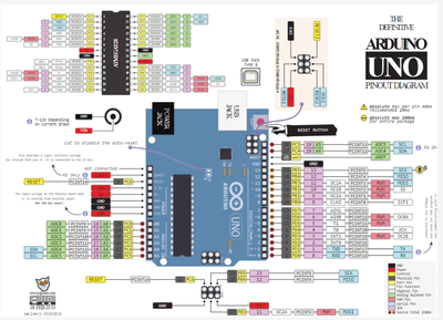
Also notice that going thru the code under Controls LCD Variables ; constant variable rs = 15 and en = 14 however the Uno schematic has them wired into A1 and A0 and I can't recognize where A1, A0 are identified in the code ( maybe obvious to someone who has more programming skills than me ) - see attached - don't know the rationale here .
In the meantime I'll wait for my new LCD Display
Thanks for your interest
Thanks for all the help , Byron
Yes, I found it after I asked the question (GPIO 14, 15 )
Also did "ping" test on the UNO R3 's - they are okay . Now I'll wait for the New LCD display and hope We resolved the issues
Back to DB1 -cable building
Just another thing to look for, the LCD can have issues if the contrast adjustment is not working right, make sure the pot works and has a good connection.
I also agree that it might be best to "build up" portions of the program to test parts of the whole (try lighting an LED, using the buttons, etc, getting the screen to work alone) and then try to tie it together.
/Brian


