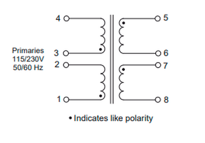
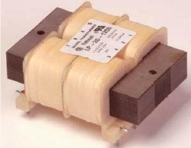
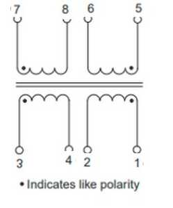
I think I can answer my own question but I'd rather be safe than sorry. Attached is the schematic from the manufacturer's datasheet. Also attached is the label on the transformer. I assume I should follow the datasheet terminal numbers and locate the terminals according to the product label.
Thus for 120V AC input I should connect the primary windings in parallel: 1 & 3 to one AC input
leg and 2 & 4 to the other leg.
For output to a full bridge rectifier to create + & - DC I should connect the secondaries in series: bridge 6 & 7 and connect this center tap to the ground of my regulator circuit; and connect 5 & 8 to the AC inputs of the rectifier.
I did an google image search,
https://au.mouser.com/new/bel-signal-transformer/signal-transformer-pc-mount-transformers/
Does this help?
http://www.hammondmfg.com/5CHook.htm
This might be better has video tutorial,
https://www.circuitbread.com/tutorials/how-to-wire-a-transformer-series-versus-parallel
@robotbuilder I saw the video and the Hammond link confirms the video so thanks for that. My hesitation is trusting the locations of the terminals according to the label on the transformer. I want to trust it but I don't know why the terminal locations on the transformer would differ from their depiction on the schematic.
I guess the schematic doesn't have to correspond with the physical connections on the transformer?
I assume they wouldn't have made a mistake but you can always check for continuity between any two terminals and perhaps you can see which way each coil is wound (clockwise or anticlockwise).
I would have to be there to play with it 🙂
Perhaps a magnetic compass and passing a current through each coil will give which way the coils are wound.
To enlarge an image, right click image and choose Open link in new window.
@cecil Logical and physical often differ, not only not unusual, it's common. Once you are satisfied you know what the primary connections are, connect them the way you think is correct, then just use a VOM to check the output. If the meter matches your research, then the research was correct, and you can carry on.
First computer 1959. Retired from my own computer company 2004.
Hardware - Expert in 1401, and 360, fairly knowledge in PC plus numerous MPU's and MCU's
Major Languages - Machine language, 360 Macro Assembler, Intel Assembler, PL/I and PL1, Pascal, Basic, C plus numerous job control and scripting languages.
Sure you can learn to be a programmer, it will take the same amount of time for me to learn to be a Doctor.
@zander Thanks again. Running this by more experienced eyes boosts confidence that I'm not missing something any pro would know. I did check continuity but that does not establish polarity. It would have been so easy to indicate polarity on the product label the way it was done on the schematic but I guess the manufacturer cannot be blamed for not catering to a novice.
@cecil Isn't it an AC transformer (trick question)? Unless I am losing it, the polarity does not matter*. Once you know via the VOM what terminals are the primary, flip a coin and connect them to the line power. Then measure the output voltages. Use a marking system to mark every wire with V and polarity, then carry on.
BTW, connect the mains power through some sort of fuse or breaker, and always observe the Electricians One Hand Rule.
* I am sure @davee will chime in to point out some esoteric reason why it does matter, and if he does, take my friend's advice, he is much more theory-oriented than I am.
EDIT: I just found the attached file on safety.
First computer 1959. Retired from my own computer company 2004.
Hardware - Expert in 1401, and 360, fairly knowledge in PC plus numerous MPU's and MCU's
Major Languages - Machine language, 360 Macro Assembler, Intel Assembler, PL/I and PL1, Pascal, Basic, C plus numerous job control and scripting languages.
Sure you can learn to be a programmer, it will take the same amount of time for me to learn to be a Doctor.
@zander By polarity indicator I mean the "dots" that mark the beginning of each winding. Then continuity will tell you the end of each winding. I think these facts are needed to wire the primary windings in parallel and to jumper the secondary windings in series. I didn't mean to say it matters which incoming AC connection is hot and which is neutral.
Hi @cecil , I've been following your post, and I think I can answer your question about what are the polarity dots for on an AC transformer..Here's a link that should clear that up for you..
https://circuitdigest.com/article/understanding-dot-convention-in-transformers
As @zander (Ron) as stated, safety is a big concern now, so please be very careful when working with voltage over 50 volts, particularity AC. Good luck on your project,
Regards,
LouisR
LouisR
@cecil Ok, what stops you from hooking it up and measuring the output?
First computer 1959. Retired from my own computer company 2004.
Hardware - Expert in 1401, and 360, fairly knowledge in PC plus numerous MPU's and MCU's
Major Languages - Machine language, 360 Macro Assembler, Intel Assembler, PL/I and PL1, Pascal, Basic, C plus numerous job control and scripting languages.
Sure you can learn to be a programmer, it will take the same amount of time for me to learn to be a Doctor.
Hi @cecil,
You have had several helpful references, and hopefully clear about the way forward. As I contributed previously, I just did a quick double check, and made a few comments below:
------------
Looking at your photo for a part number, a quick Google shows:
https://www.mouser.co.uk/datasheet/2/643/ds-st-lp-series-1633375.pdf
which I presume is what you expect.
-------------
It is not unusual for physical layout and a schematic to be arranged differently, but hopefully we can trust they have matched up the pin numbers!
---------
I have to admit I would not personally have picked the word 'polarity' to talk about the direction of the windings, but for single phase at least, it makes 'sense' when discussed in the manner of @inst_tech's Circuit Digest .. i.e. matching the dots means the windings have the same 'polarity' (e.g. positive half cycle) at the same time, so hopefully all is clear and straightforward.
----------------------
You proposed:
Thus for 120V AC input I should connect the primary windings in parallel: 1 & 3 to one AC input
leg and 2 & 4 to the other leg.
For output to a full bridge rectifier to create + & - DC I should connect the secondaries in series: bridge 6 & 7 and connect this center tap to the ground of my regulator circuit; and connect 5 & 8 to the AC inputs of the rectifier.
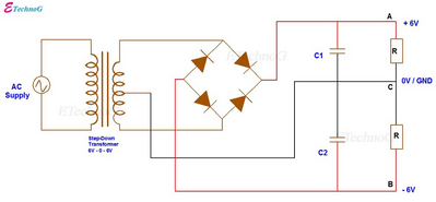
I agree with your proposal assuming your secondary connection is something like the diagram below, and you have smoothing capacitors in the positions indicated by the resistors "R" ... obviously taking care to get the polarity of the capacitors correct!
Obviously your secondary is 10Vac + 10Vac, (not 6Vac + 6Vac is shown in this 'borrowed' diagram), so your output voltages will be proportionately increased, and when smoothing capacitors are added, the outputs should be about +14V and -14V respectively on no load.
-------------
Hope this helps.
Good luck, Dave
@zander I did hook it to the mains as I originally proposed and the measured outputs are as expected. As always, I learned alot by double checking here first.
@davee "polarity" was my error in diction. The picture I posted to show the labeled positions of the terminals was grabbed from the Internet; my transformer is an LP-30-400 from the same manufacturer and series.
I do have a question about the example schematic you posted. You say smoothing capacitors in the positions of the resistors shown. Would these be in addition to C1 and C2? I read about smoothing capacitors, decoupling capacitors, and bulk capacitors but I only have a very sketchy idea of the difference. I've also read that ceramic capacitors should be placed between the rectifier diodes and larger electrolytic capacitors but I've never seen an example of that in a schematic. Maybe that's because I haven't looked at enough schematics. Then there is the requirement of a small capacitor near a linear voltage regulator input if the input is "too far" from the smoothing capacitor. I struggle to reconcile all the advice at once.
@zander ...
@davee ...
I read about smoothing capacitors, decoupling capacitors, and bulk capacitors but I only have a very sketchy idea of the difference.
...
This is really where it would be nice to have an oscilloscope. You can check each point in the circuit to see what effect if any a particular capacitor (or some other electronic filter configuration) is making. It is nice to see what is going on rather than guessing.
Hi @cecil,
Looks like I have made a confusing statement, sorry 🙄. I wrote my reply in a bit of hurry, and the image when imported onto the forum is very small, so I completely missed seeing C1 and C2!
In the past, I have usually made a first draft of a document, and left it to 'mature' for a while, so that I can reread with at least some chance of seeing the 'sillies'. I also often passed the draft to a colleague (and they did the same in reverse), if it was for 'outside' consumption. Forums and the like can give more timely answers which is an upside, but are not very amenable to the error catching, which is a downside .. occasionally more speed also means more errors.
==========
But you have raised a valid question as an accidental consequence.
smoothing capacitors, decoupling capacitors, and bulk capacitors but I only have a very sketchy idea of the difference. I've also read that ceramic capacitors should be placed between the rectifier diodes and larger electrolytic capacitors
"smoothing capacitors" and "decoupling capacitors" are essentially doing the same thing, albeit from different perspectives, namely acting as charge reservoirs which can reduce the local voltage changes, a bit like a controlled dam + reservoir on a river can be used to smooth out the downstream river flow, thereby reducing flooding and drought.
"smoothing" capacitors is usually used to describe those used in the process of converting AC into DC, of which your power supply is an example, so called because they are "smoothing" the humps into a steady voltage.
Since the "humps" are usually fairly low frequency .. say 100Hz or 120Hz .. the capacitors used for this job need to have a fairly large capacitance to be able to store enough charge to last from one hump to the next .. typically 1000 microFarad (uF) as a minimum, often more. This means these capacitors are typically electrolytics whose characteristics are suitable for the lower frequency demands, but do not perform well in situations involving higher frequencies.
"bulk capacitance" is not a term I have often seen used, but usually refers to the large capacitors used in such smoothing tasks, and found in DC power supplies with AC input.
"decoupling" capacitors are far more wide spread in electronic circuits. Whenever the currents and voltages in a circuit are changing, the changes cause many effects, some of the effects are desired, but others may not be. For example, when a CMOS logic gate changes state (e.g. high to low), there is a short period of time in the middle of the transition whilst it will conduct current, plus the changing of state involves charging and discharging small local 'intrinsic' capacitors which are formed 'accidentally' as part of the circuit. This means that during the transition, the device will draw current, and that current can be remarkably high, albeit only for a fraction of second. However, that transient current must be carried to the gate by wires (I am using "wires" to include PCB tracks, pins in the chip and so on.), and wires have both resistance and inductance, the combined effect being described as impedance. A current flowing through an impedance will result in a voltage drop, so that during the transition, the 'real' power supply voltage at the logic gate is different from the steady state, and in adverse cases, the difference can be enough to confuse it between high and low states. Analogue circuits suffer in similar manners, such as an amplifier turning into an oscillator.
There are other common applications of the same principle, but this sermon is long enough without me attempting to describe them all!
To minimise these effects, capacitors can be connected across the power input pins of the device, to act like a local reservoir of charge, and therby reduce the variations of voltage seen by the active device. Since most electronic circuits have multiple active devices, it is common to provide each logic chip with at least one 'personal' capacitor, thereby 'decoupling' its current demands from that of its colleagues.
Decoupling capacitors are most commonly used to deal with higher frequency current demands, which for contemporary chips goes from kHz through to GHz. A quick rule of thumb would use a 0.1 uF ceramic capacitor for the lower part of this range and 0.001 uF - 0.01 uF ceramic capacitor for the middle upwards of the same range. Sometimes a 0.1uF and 0.01uF (say) will be used in parallel. This is because the internal structures mean the smaller value capacitors have lower inductance, and 'fill in' for some of the limitations of the larger colleagues. In addition, an electronic circuit board may have one or more electrolytics, say 100 uF, shared among a small number of chips, to provide low frequency decoupling. At low frequencies, the inductance across a few millimetres of PCB tracks is less important, but the capacitor helps to reduce the effect of (say) a few centimetres of wire to the power supply capacitors. Of course, the power supply "smoothing" capacitors will also play a part in assisting the "decoupling" tasks when the connection wires are kept short.
Voltage regulators, like the 7805, often require decoupling capacitors on both input and output pins to prevent them oscillating ... the manufacturer's data sheet is good starting place for advice.
------
A further related task for capacitors, particularly small-ish value capacitance value, ceramic capacitors, is to provide some protection against external transients, such as random voltage spikes, originating from distant events like lightning strikes or flashovers, transmitted along the mains power lines. In some cases they are connected in parallel with the component, with the aim of reducing the peak voltage across the component and hence reducing the chance of it failing. In other cases, the capacitor may connect to the 0V or ground line, with the aim of safely redirecting the energy of the voltage spike, before it reaches more sensitive circuitry. The extent to which these are needed depends upon the environment the equipment is used, as the risks and the consequences can vary widely.
Initially, I wouldn't worry too much about adding these capacitors, unless you are following a design which has specifically included them for a reason.
-----
When you say "ceramic capacitors should be placed between the rectifier diodes and larger electrolytic capacitors", I assume you mean physically between, as in along the 'path' or flow through the circuit, not actually in series. The capacitors should be in parallel.
------------
I hope that gives a little general background. In reality, when building a 'one-off', it is possible to omit many decoupling capacitors, etc. without stopping the unit working, so don't get over worried. Instead, take reasonable precautions, probably over providing the number of decouplers, and be ready with a few spare capacitors for a judicious upgrade!
The result of missing a decoupler can be a unit that fails under certain conditions, e.g. as the battery ages, but should still be serviceable. For production engineers, the experience can be that the one or two prototypes worked well, but 80% of the first production batch fail ... or if they are really unlucky, 10% of them fail when out in the field, possibly thousands of miles away.
--------
And as a final note, I agree with @robotbuilder .. an oscilloscope can be really handy to see what is happening, though it can also lead you down the garden path, so don't believe everything you see on the screen.
Best wishes, Dave
@davee I am saving that reply for my education. My memory must be totally shot, or we did not learn this in the 4 years I studied electronics in high school. 50% of each day was spent in the electronics lab, between the classroom and the workbench. Either my memory is shot, or we didn't get taught this or maybe it wasn't known yet. It was about 1960.
First computer 1959. Retired from my own computer company 2004.
Hardware - Expert in 1401, and 360, fairly knowledge in PC plus numerous MPU's and MCU's
Major Languages - Machine language, 360 Macro Assembler, Intel Assembler, PL/I and PL1, Pascal, Basic, C plus numerous job control and scripting languages.
Sure you can learn to be a programmer, it will take the same amount of time for me to learn to be a Doctor.


