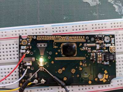
Hello,
I'm still working on my custom photographic date back. (for those at the back who don't remember and also)
But I think I broke the Minolta date back I'm trying to control.
In fact the light bulb is not turned on anymore when I short the yellow and black cable.
I've uploaded a HD image here so you can zoom in :
CLICK HERE
So I've taken out my multi-meter and made some measurements.
- All the resistors seem to be working.
- All the ceramic capacitors seem to be working.
- The screens and the light-bulb are working.
And then there are the 7 SMD components which seem to be transistors:
Some are marked "SG" others "ZQ".
From this page it seems to be SOT-23 NPN and PNP transistors.
So I went to youtube and watched a few videos on how to test transistors.
For the 5 firsts transistors (numbered 1 to 5 on the image) I got a reading of around 800 (ohms ?) between base/collector and base/emitter
For the transistors numbered 6 and 7 I got totally different readings:
- For the number 6 (PNP) I got reading of 700 between base/collector and a reading of 016 (ohms ?) between base/emitter (my multi-meter bipped)
- For the number 7 (NPN) I got reading of 700 between base/emitter and a reading of 0 (ohms ?) between base/collector (my multi-meter bipped)
My two questions :
Are those SMD component transistors ?
Are they working correctly ?
Thanks 🙂
@nicolas I am a photographer (pro at one point) and a tech guy, but I wouldn't know where to start with that. I would be tempted to go to a pawn shop and buy the same camera with a working back.
First computer 1959. Retired from my own computer company 2004.
Hardware - Expert in 1401, and 360, fairly knowledge in PC plus numerous MPU's and MCU's
Major Languages - Machine language, 360 Macro Assembler, Intel Assembler, PL/I and PL1, Pascal, Basic, C plus numerous job control and scripting languages.
Sure you can learn to be a programmer, it will take the same amount of time for me to learn to be a Doctor.
Hi @nicolas,
I know nothing about camera circuits in particular that might be helpful, but given the number of different transistors that have been produced, identifying a particular model on the basis of just two letters isn't likely to be easy, though if two devices have the same code, it is probable they will be the same type. Furthermore, sometimes the letters refer to factory batch codes or similar internal coding.
Whilst it is plausible that the devices with three legs are transistors, they could be bipolar (NPN or PNP) or FETs (p-channel or n-channel), plus some rarer types. Each of these groups have very different characteristics. Some failure types can be found with a simple resistance check, but only if the transistor is isolated from the circuit or the circuit schematic can be checked.
Measuring the resistance between a pair of transistor leads whilst it is soldered into a circuit often produces misleading results, since other components will also be connected in parallel.
Also, note that for bipolar transistors, the resistance depends upon which way round the probes are connected, as well as what voltage the meter is applying to the device.
The very low resistance values you quote are slightly suspicious, but probably due to other components in parallel.
-----
Sorry, but in short, unless you can find or create a circuit diagram for your board, I think you will have a hard time diagnosing a problem. Of course, you might have a massive stroke of luck and find a solution, but personally, although I have never visited a pawn shop, I think Ron (@zander)'s suggestion is probably more plausible.
Best wishes, Dave
@nicolas The part where you pointed Transistor 4, 5, 6 and 7 seems to be a coil less boost converter (the neon bulb needs about 50V). Zero Ohms on base/emitter on T6 and T7 is very suspicous.
It should not be too complicated to reengineer the schematics of this area to find out how it works. Then to check trigger signals for the HV from the glued IC.
Just in case you are very unlucky - you might have killed an input of the IC with a conductive finger tip and relatively high voltage around. In this case, the only solution would be to find another camera on ebay...
Rule of Thumb in hardware/software engineering:
From the estimated time to complete a project you need:
5% for the engineering itself
95% securing everything against any strange idea users can have
and the remaining
150% for finding and fixing bugs that you thought never could happen
Hello everyone !
thank you for all your answers, so I guess I'll have to find a new working data back 🙁
I'm able to light the bulb by applying 3.3v to its legs, I guess it means the bulbs doesn't need 50v ?
Thanks again
@nicolas, on your photo it looked like a kind of neon - gas - discharge bulb. When you can light it with 3.3V it is most probably an incandescent lamp. Sorry for your effort on my "wild" guess.
Rule of Thumb in hardware/software engineering:
From the estimated time to complete a project you need:
5% for the engineering itself
95% securing everything against any strange idea users can have
and the remaining
150% for finding and fixing bugs that you thought never could happen


