Hello
as a mechanical guy , I really enjoy this forum and the content from Bill
i am looking for an easy way to convert a -5V to +5V signal into a digital signal I can log
regards
brad
What is the source of this -5v to +5v ?
Are you going to use an Arduino and its analog pins as input?
Often the more complete the description the more likely you will get the answer you want.
We need to know a few more details. Is this a digital +5/-5V signal, or analogue with that max amplitude? In either case, what's the highest frequency you expect to see?
"A resistor makes a lightbulb and a capacitor makes an explosion when connected wrong"
"There are two types of electrical engineers, those intentionally making antennas and those accidentally doing so."
Yes it is a bit hard to answer without more details.
However the problem itself seems interesting and I thought there would be a professional electronics expert that might have offered a solution.
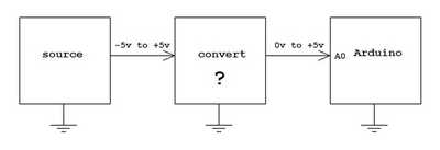
How would you wire up a circuit to act as a converter as shown below.
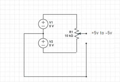
As a source I decided to use this one and test out some ideas.
Hi all, the system measures the linear speed of a vehicle using a light source , the lateral and longitudinal velocities give rise to signals proportional to the speed.
These two signal depending on the movement of the vehicle can be positive or negative ( so moving to the left could be a negative -5V and to the right a positive +5V) , the same applies for the forward and backward movement.
By combining the two velocities with a simple Pythagoras (x^2 +y^2 = R^2) the slip of the vehicle is given
As we cannot handle the negatives , I thought we can step up the voltages so that I can read them with an Arduino
regards
Brad
@zaeng
As we cannot handle the negatives , I thought we can step up the voltages so that I can read them with an Arduino
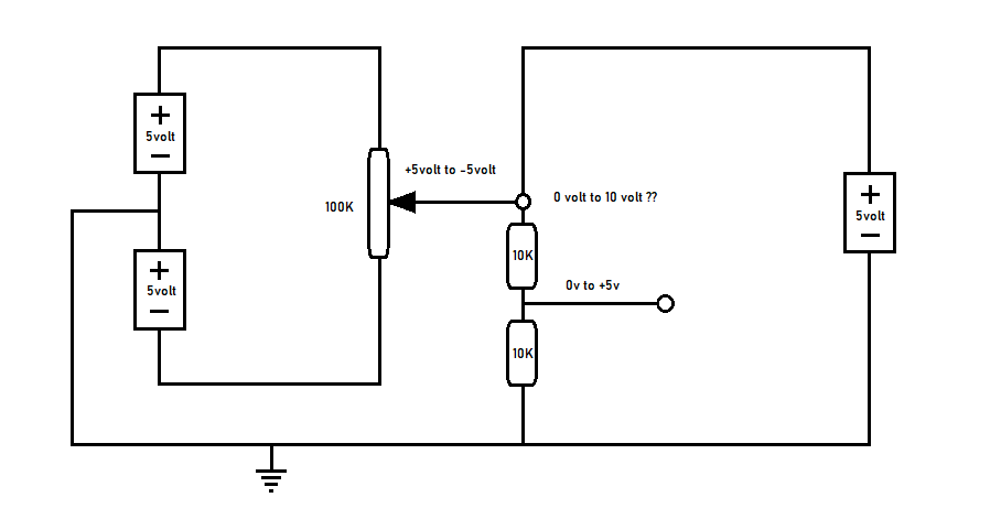
My thought as well. Lift -5v to +5v into 0v to +10v. You then use two resistors to make a voltage divider to reduce it to the 0v to 5v range for the Arduino. I would want to build a test circuit however to make sure the solution works which if no one beats me to it first (go for it) I will try and test tomorrow.
Oh... right. robotBuilder is correct. You should be able to hook up a simple voltage divider for this. You can actually simplify to a single voltage divider, "pulling up" your signal to 5V and measuring in the middle.
You also need to make sure the arduino's ground is common with the signal's ground, you don't want to accidently introduce a massive signal voltage differential here, or you will fry the arduino.
Driving current like this into some sensors can do "bad things", although sufficiently large resistors can help.
"A resistor makes a lightbulb and a capacitor makes an explosion when connected wrong"
"There are two types of electrical engineers, those intentionally making antennas and those accidentally doing so."
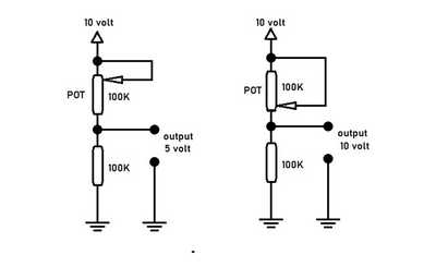
Tried the circuit below with real parts and it seemed to work although I smoked a POT accidently.
Maybe someone can try it with one of those circuit simulators?
hello , i hope you are well
A stint of Chemo is keeping me from my hobby
Can you maybe go a step further and show me a real setup , say using 1 Arduino as the supply of the 5V (not fluctuating) and another where I have a potentiometer taking 5V in and dropping the voltage
So the end goal would be also to see a max of 10V when the resistance of the pot in minimum and a min of 5V when the pot is max resistance ?
I am thinking of trying an operational amplifier C4570C
Kind regards
Brad
Maybe I will experiment on it later. Anyone else want to figure it out?
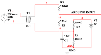
This might be of use,
https://www.researchgate.net/figure/Circuit-Diagram-for-Voltage-Measurement_fig3_286469531
So you have a -5v to +5 signal that you want to change to 0 to +5volt signal so it
can be read by a analog input ? A digital signal only has two states so you really
don't want a digital signal.
I think a couple of op-amps would work one to level shift then use a resistor divider with a op amp as a buffer on the output.
The nice think about op-amps is they are high impedance inputs and will not load your input.
level shifter https://daycounter.com/Circuits/OpAmp-Level-Shifter/OpAmp-Level-Shifter.phtml
voltage divider with a buffer https://electronics.stackexchange.com/questions/91230/op-amp-gain-less-than-1
I am looking for an easy way to convert a -5V to +5V signal into a digital signal I can log.
The system measures the linear speed of a vehicle using a light source, the lateral and longitudinal velocities give rise to signals proportional to the speed.
These two signal depending on the movement of the vehicle can be positive or negative ( so moving to the left could be a negative -5V and to the right a positive +5V) , the same applies for the forward and backward movement.
By combining the two velocities with a simple Pythagoras (x^2 +y^2 = R^2) the slip of the vehicle is given.
As we cannot handle the negatives , I thought we can step up the voltages so that I can read them with an Arduino.
Can you maybe go a step further and show me a real setup , say using 1 Arduino as the supply of the 5V (not fluctuating) and another where I have a potentiometer taking 5V in and dropping the voltage.
So the end goal would be also to see a max of 10V when the resistance of the pot in minimum and a min of 5V when the pot is max resistance ?
I am thinking of trying an operational amplifier C4570C.
Perhaps if you reveal the actual hardware so we know what you mean by "using a light source" to measure linear speed? Complete information is needed if you want a better response and sustained interest by others. This is not a problem I have had to solve myself as self taught hobbyist. The internet doesn't always provide solutions because electronic engineers don't always publish solutions even if, given sufficient information, they would have no trouble working out a solution. I don't know how many if any members on the forum are electronic engineers.
Your last request (10v max to 5v minimum) is a simple circuit.
And yes I think an op amp may be part of a proper solution.
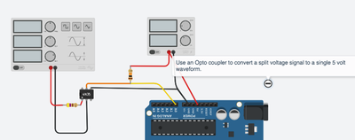
It should be possible to use an opto coupler (opto isolator) like a 4N35 to translate and isolate the split signal to a 0 to +5 volt signal. The opto's diode input would drain approx 20 mAmps from the 10 volt (in total) signal. This should be enough to drive the photo transistor's open collector output to ground but the resulting signal would be opposite polarity.
https://www.instructables.com/4N35/
@nowear Thank you , I will try your suggestions, and thank you for the link
if you are really interested in the device giving the signal please drop me a reply and I will find a document
when I talk digital signal the end goal is to convert the analogue signal to a CAN bus message using a device called a LTC lin to can

