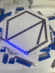
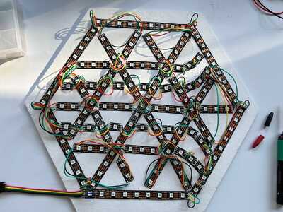
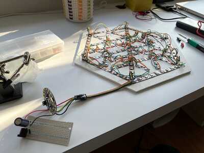
I am in the middle of making a sign out of DotStars from Adafruit. But whenever I went and cut and soldered two strips together the second strip will not light up.
I'm guessing I messed something up with soldering, but before I go messing other things up by undoing my work, I wanted to ask for suggestions here.
What would cause this? Bad connection?
The code should be fine, it is set up to drive the whole 200+ LEDs, and was working prior to me cutting the strip.
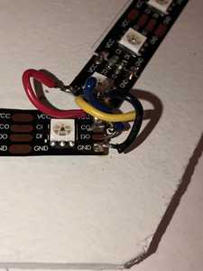
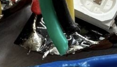
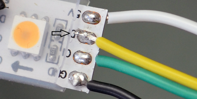
I've attached a few pictures. I had to solder one of the wires on the back because the pad at the end of the strip came off on the top side of the strip.
Side note: The wire I'm using, also from Adafruit, is very difficult to bend and work with in these tight spaces. Do you have any other recommendations? Or, indeed, another way to make shapes out of DotStars, if there is one.
Thank you all!
Use a VOM to check the voltage at both ends of the connections. Sort of probe or push on the solder joints to make sure no loose, or rosin joints.
First computer 1959. Retired from my own computer company 2004.
Hardware - Expert in 1401, and 360, fairly knowledge in PC plus numerous MPU's and MCU's
Major Languages - Machine language, 360 Macro Assembler, Intel Assembler, PL/I and PL1, Pascal, Basic, C plus numerous job control and scripting languages.
Sure you can learn to be a programmer, it will take the same amount of time for me to learn to be a Doctor.
The code should be fine, it is set up to drive the whole 200+ LEDs, and was working prior to me cutting the strip.
OK, then the LEDs and the traces were both fine beforehand. So, it's unlikely to be a software problem unless the sketch relies on a fixed number of lights.
I've attached a few pictures. I had to solder one of the wires on the back because the pad at the end of the strip came off on the top side of the strip.
Um ... was that either the red or the black wire ? That could compromise the following string.
Try connecting the power to the end of a strip that hasn't been soldered and see if that strip lights up. It's probably a soldering problem, most likely that the iron was too hot and damaged the traces or burned off the terminals on the cut point.
You may need to cut off the end light on each string and re-solder them together. If you need a specific count on each side and you have some left over, you could glue the back of the strips onto some paper and glue a single light on the end of the paper strip. Then carefully add a small daub of solder to bridge the gap between the singleton and the last light on the paper strip.
Then carefully solder the strips together again.
Double-check the sketch to make sure there's no dependency on the count of lights.
Anything seems possible when you don't know what you're talking about.
Hi Aaron @a2rpriest,
I have never come across these devices before ... I had to Google to find out what they were .. so I can offer some imagination of how they behave ... others may be able to offer direct experience.
It seems likely you have a wiring problem ... e.g. a sneaky thin sliver of solder could short two pins
Perhaps more likely you have a mechanical break. I can't see the reverse side of the strips, but clearly each LED has a small microprocessor and other parts hidden away somewhere, and these must be connected with very thin tracks, since the space is very small. They will be vulnerable to stresses applied to the pads. As you say, it is very difficult to wire them using the wires you have.
I sympathise with the problem you face ... and my first check would be to look very carefully at your connections.
I assume you have (at least) a multimeter, but probably not an oscilloscope. Thus you can check for 5V power to all of your connected strips.
I would use the multimeter to check that the 0V and 5V are providing power to the unlit strip. Check that 5V reaches the 'far' end of the unlit strip.
-------------
If this fails to find the culprit, then read on. Your multimeter checks should have revealed any problems with the 5V or the 0V line, so assuming these were fine, we can concentrate on the data lines.
--------------
Say you have two strips of 10 LEDS each connected as shown in your photo,
with the individual LEDS of each strip numbered A1 .. A10 and B1 .. B10,the output pins of A10 are handwired to the input pins of B1.
Then I assume A1 .. A10 is lit, B1 .. B10 are not lit.
Unfortunately, two LEDs are still both 'chief suspects' of suffering mechanical damage:
- A10 ... which may be broken with respect to the connections to CO or DO, but otherwise intact to light its own LED
- B1 .. ... which may be broken with respect to the connections to CI or DI, or with respect to the circuit on that link generally
I suggest you disconnect the links CO -> CI and DO -> DI, at one end, say CI and DI.
Now you need to use a third strip C1..C10 , provide it with 5V and 0V power supply connections.
Then do two 'tests' ...
- for the first test, use some temporary links .. connect DO and CO from A10 to DI and CI of C1
- if C1..C10 light, then A10 is probably OK, if C1..C10 do not light, A10 is probably broken
- for the second test, replace A1..A10 with C1..C10
- i.e. disconnect the control from your Arduino to CI and DI from A1 and connect the Arduino links to C1 ... at this point C1..C10 should light when powered
- Connect CO and DO from C10 to CI and DI of B1 ... now C1..C10 and B1..B10 should light when powered ... if B1..B10 do not light (but C1..C10 are lighting), B1 is probably faulty.
---------
Sorry this is rather 'wordy' .. I hope you can follow it through.
As for the general wiring question, you have my sympathies, but I think you need to realise these devices are probably mechanically fragile. Personally I think I would look to mount them on a non-conductive backing board. Thread the wires through holes in the board, so the majority of the wire length is under the board. This should reduce the chance of the pads being pulled off.
It might be possible to drill a small hole in each pad, so the connection wire passes through it ... but this obviously implies you have ensured there are no other connections or components under the pad areas. Otherwise, push the bare wire through the baseboard and bend it to touch the pad before soldering.
The CI->CO and DO-DI wires could be much thinner, as the current is minimal. The AWG 30 wire associated with wire-wrap would be fine, although you will need a suitable wire stripper tool ... our learned host Bill has discussed it on this forum.
The 0V and 5V wires potentially have a much higher current requirement .. an individual LED or three will be happy with thin wires, but 200 LEDs implies several Amps. I think the baseboard may be something of a saviour here. Have separate thin wire feeds to each strip under the board, all meeting up at convenient points to go the power supply through suitably thick wires. For a strip of say 10 or more LEDs, it may be a good idea to connect 0V and 5 feeds to both ends. When you have a strip lit, use multimeter to measure the voltage drop across the wires to look for any wires that are dropping an excessive voltage.
Hope these suggestions are helpful .. mechanical construction is definately not my forte, so feel free to improve on them.
Best wishes and good luck. Dave
Thank you all for your suggestions! Very helpful.
Side note: @davee I do have a Seeed Oscilloscope, but I'm not very skilled with it. I used a multimeter as you suggested.
Side Note 2: I double checked the code, there is no dependency for an exact amount of LEDs. I put a max of 250, but the code should update any LEDs up to that maximum.
Multi Meter:
Between VCC[0] and GND[15] I got ~5v.
Between CO[0] and CO[15] I got ~5v. But it would alternate every other LED. [0] to [1] would show 0v, [0] to [2] shows 5v.
Between DO[0] and DO[15] I got ~5v.
Seemed like there was power going to everything, even over my terrible solder work.
Still could not get the rest of the lights to turn on. One LED randomly turned on and white, but couldn't reproduce that.
Trying Other Things:
I went to unsolder and test different connections, like Dave said, and I found that the pads on these connections are very flimsy. Another pad came off at B-Strip CI[0]. Once the conductive pad rips off there's no way to connect a wire to the strip again. Very frustrating because I have ~30 of these connections to make. If this continues to happen I won't have anymore good LED strips. Obviously I'm doing something wrong.
PCB:
I'm wondering what the cost of getting a custom SMD PCB for this would be? That would be a totally new world to me. And this is rather large hexagon shape 10.5"x12". Is that a crazy idea? How is done in the hobby world traditionally?
Hi @aaron,
Sorry to hear you didn't manage to get an answer.
With an oscilloscope, I would be tempted to start looking for data instructions flowing or otherwise along the DI/DO lines and clocks (presumably) along the CI/CO. You probably can't do much harm trying (as long as the probe doesn't short anything), but it is probably not the easiest way to learn about scopes.
Looking into the words on the web, I realise these are actually flexible PCBs, which are even more notorious than their rigid cousins for being flimsy.
My feeling is that do not really expect to be soldered ... at least not with 4 independent wires .. 4 thin wires mechnically supported and soldered in a well controlled, automated system in some way would be different ... otherwise, I think they expect connectors.
I note Adafruit talk about JST connectors for at least some of these LED strips ... I am not sure if they included the type you have, but they certainly have 4 'pins' looking remarkably similar. I am not sure they will meet your mechanical spacing requirements, but maybe give a rough direction to consider.
You might be able to find a 'direct PCB edge connector' that would do.
Unfortunately:
- 2.5mm pin-pin spacing is less common than 2.54mm .. it is feasible, over only 4 pins you could get away with this discrepancy .. I haven't checked
- most PCBs need more than 4 pins, so hacksawing larger connectors down may be required
- The strips are probably thinner than a rigid PCB, so it may be necessary to 'pack out' the slot
- PCB direct connectors are also 'out of fashion' compared with indirect, so your choices of off-the-shelf in cheap small quantities could be a challenge.
I came across this oddity which looks like 2 x 4-ways ... but have no idea if it would be useful.
https://uk.rs-online.com/web/p/edge-connectors/1742035 (UK website but presumably available elsewhere)
-------
Custom PCB ... not my speciality ... I have ordered PCBs in the past for work, but only when my company was paying. Obviously it depends upon the depth of your pocket, but that board is fairly large, although it is presumably only 1/2 layer, so I guess it will not be cheap ... particularly if you want if for this Christmas.
From a technical view, it still looks a bit tricky as the solder pads are on the top of the tape. Thus you will need to make some short wires which go from the board to the pads. That is not much different from my suggestion of baseboard in my last post.
Good luck with your search. Best wishes, Dave
@davee Hello again, two years later. I’ve been busy with my first kid.
Thank you for your response. Sorry I didn’t respond earlier.
I switched to stranded wires to solder to the pads of the dotstars. And that actually worked! Until it didn’t.
I tested everything. Soldered hundreds of connections. And then simply switched the Adafruit playground to be soldered instead of breadboard and alligator clips. And that’s when it all fell apart.
As soon as I did that, nothing lights up. It was working minutes before. And now nothing.
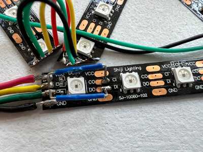
I read online that I may have destroyed the first dot star and should try jumping over the first CI DI connectors (photo 2). No luck.
At this point I’m tempted to rip everything off and use it for spare parts. But figured I’d ask here one last time.
Multimeter shows connection all the way down the chain for all 4 leads.
@aaron Almost impossible to help without an identical setup, but when looking closely at one of your pictures it looks like there are one or more shorts. You can use a magnifying glass and verify there are no shorts. These are often called solder whiskers.
First computer 1959. Retired from my own computer company 2004.
Hardware - Expert in 1401, and 360, fairly knowledge in PC plus numerous MPU's and MCU's
Major Languages - Machine language, 360 Macro Assembler, Intel Assembler, PL/I and PL1, Pascal, Basic, C plus numerous job control and scripting languages.
Sure you can learn to be a programmer, it will take the same amount of time for me to learn to be a Doctor.
Hi @aaron,
Congratulations on your increasd family responsibility, but commiserations that the LEDs have failed.
Unfortunately, you really need to use an oscilloscope to look for data signals, or perhaps more accurately, the lack of them, otherwise it is like trying to find something in the dark. I note you mentioned you had one. This could be an opprtunity to hone some new skills.
Bear in mind, if the first LED has failed, it may be 'shorting' out the data signals, so that jumpering to next one will not help. Equally, can you be sure the controller board is sending out any data?
I suspect I have already given as much help as possible before, but I assume you have read that again, so unless you have any more specific details, I doubt if I can help, sorry.
Good luck, Dave
The soldering looks a bit scary in places, that might be a source of the problem?
I noticed the blue wires are not stranded. Solder can look like it has attached when in fact it hasn't. Without a naked eye inspection it would all be guess work from here.
I haven't used these strips myself so I am just assuming the wiring is correct.
With multistrand wires I twist the cut off ends between two fingers. However I noticed they didn't bother in the example below.
https://learn.adafruit.com/roll-up-video-light/prepare-led-strips
I add solder to the wire and the target surface separately and then hold them together and apply the heat. The instant the solder melts together I withdraw the soldering iron tip. If you mess with it you end up with a dry solder joint or as I did below overheating the copper strip.
Its been some years since I last did any soldering but I grabbed some wire as a demo with the result below.
The soldered wire was too long so I shortened it which is easiest to do after adding the solder.
Actually my unregulated cheap soldering iron was too hot and I burnt the adhesive holding the copper strip to the breadboard! I usually did some practice before tackling a big soldering job.
You just get a feel for it after a while. Solder will run to the hottest part of a surface. I used to do a lot of bronze soldering of metal piping which again becomes easy and quick with practice.
Then again maybe the soldered connection have nothing to do with the problem!!
Thank you @zander, @davee, and @robotbuilder for your help.
First, @robotbuilder, I never knew what caused the rough look on solder. Thank you!
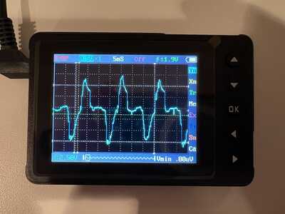
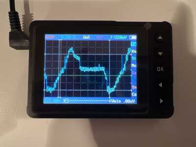
@davee you inspired me to pull out my ocliyscope and give it a go. It's quite intimidating. I have a Seeed DSO Nano. I watched a few videos and tried to learn what is going on, but when it comes to setting actual settings for the CI and DI pins I'm just guessing.
I managed to see a spike several times on the scope when I'd press a button to send a new command (change the brightness of the lights). But then after I messed around with the settings I never saw it again.
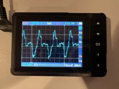
I've attached a few pictures. However, I fear I am simply showing noise. The patterns from the CI and DI pins (A1 and A2 on the Playground) look very similar to me. Is that data?
CI Pin:
DI Pin:
Other picture:
Lastly, do you have any resources you'd recommend for learning to use an ocliyscope?
Thanks again!
Hi @aaron,
I am not sure, but I don't think you have connected the earth part of the probe. The pattern looks a bit like mains hum pickp.
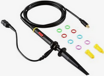
I have borrowed the picture of a typical probe:
Note the dangly lead coming from the side of the probe, ending in a small crocodile clip. That needs to be connected to the ground/0V line of the circuit, preferably physically near to where the main probe is clipped to.
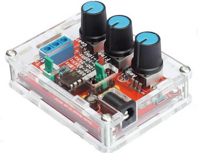
I admit, you might struggle first time with a circuit whose waveforms are not familiar. You might consider acquiring a small circuit board that produces waveforms ... maybe something like:
www.amazon.co.uk/Lysignal-XR2206-Precision-Function-Generator/dp/B073WVBRTM/ref=sr_1_15?keywords=waveform+generator&qid=1699494987&sr=8-15
might be a good low cost start.
You can also the probe the outputs from an Arduino or similar board when it is outputting a waveform.
Similar boards are available from most of the usual places - some have just the board, not the perspex case. The particular reference was not a recommendation of that vendor, who just appeared as 1st in my search on Amazon.
===========
Sorry, I have been using scopes from time to time for over half a century, so I don't go looking for tutorials or courses. However, I just did a quick Google for YouTube oscilloscope tutorial and a number of choices appeared -- the first one I looked at a few seconds was:
which seemed to be explaining the basics.
I suggest you check out this one, and similarly use Google to find a few more. I don't expect they will all be brilliant, but hopefully you can track some good ones down.
Some good starting phrases to type into Google search include:
dronebot-workshop oscilloscope --- I am sure these will be excellent!!!!!
toptechboy workshop oscilloscope -- Paul usually explains things in good detail ... the one's I saw in the list are probably experimental rigs he is discussing, and he is using a scope to show what is happening, so these may make more sense after watching a couple of scope introductions.
--------
So try having a look for yourself. If there is something you can't see explained, (after doing a bit of searching around), try asking a specific question here.
--------------------------
Note that whilst you have an 'economy' scope, compared to many you may see the presenters use, the principle is the same. The extra cost of the bigger scopes usually means multiple channels, and the ability to see higher frequency signals, plus of course some do party tricks that make life easier. But whilst a scope might cost say $50 or $50,000++, they are all aiming to do similar task and have the same basic controls.
Sorry this will be a learning curve, a demanding one at that, and before you start to look at your problem, but it is a really useful one! Don't expect to master everything at once ...take it slowly and the parts will gradually fall in place.
Best wishes and good luck, Dave

