I was wondering if somone could help me by answering a couple of questions. So I've watched Bill's video where he shows the Star Wars song played by the Arduino. I have no trouble getting it to work with an Arduino Uno. I want to get it to work as a standalone circuit with the ATMega328P-PU.
This is where I got my chips:
https://www.mouser.com/ProductDetail/Microchip-Technology-Atmel/ATMEGA328P-PU?qs=K8BHR703ZXguOQv3sKbWcg%3D%3D
I thought I was buying chips with the Bootloader already on it. But after a lot of trial I believe that the Bootloader wasn't on it. I keep on getting errors about the software and the chip not being in sync. I've been trying to load the bootloader on the chip for days. I tried the latest version of the Arduino IDE 1.8.11. That didn't work. From all the forum posts I've read there is sometimes some trouble with different components of the software not being updated at the same time.
At one point I had what I thought was a successful bootloader download. I have the verbose output from that apparent success saved in a text file. But I still couldn't get the sketch to go to the chip.
I don't think it's a problem of wiring (I suppose I could have a bad component). I think it's a software issue. I tried going back to version arduino-1.0.6-windows.exe yesterday and got some kind of USB error.
I'm running Windows 10 64 Bit. Can you tell me what version of the Arduino IDE you are using to load the bootloader? Did you have to install any separate drivers other than what comes with the IDE? And are you running Windows 10? I want to basically copy the setup from someone who I know is able to load the bootloaders. Thank You.
Jonathan
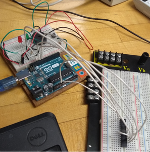
If this attaches successfully this is the circuit I had set up when I thought I had the successful bootloader upload.
Hello Jonathan! I am one of the moderators of the forum and I'll be glad to help you with your effort to load the bootloader on to your ATMega328P chips. I just went through the same confusing and frustrating effort that you've just encountered. But first let me make a comment from a moderators point of view.
You had made two nearly identical posts just minutes apart that wound up in the moderators bucket so to speak. The reason being that you are a relative newcomer to the forum and your posts had links in them. In your case the links were to Mouser where you purchased your chips. Posts from newcomers that contain links are automatically flagged as needing to be moderated so that someone can be sure they are not links to something not appropriate. Later on posts don't get moderated just because they have links in them.
I have approved one of your posts, this one that I'm responding to, but have deleted the other since it was really a duplicate of this one, but just mentioned a particular members username.
If you'll look at the start of this reply you will see that I placed the "@" symbol in front of your username. That causes the forum software to send you an email that someone has replied to your post and referenced your username. Without the "@username" you would not be notified and to see any responses/replies you would have to return to the forum to see what may have been posted.
So all that being said, Welcome! To what I think has become an excellent forum for finding help on your Arduino adventures and making new friends around the world. And if you have yet to notice, we do have folks from everywhere.
Now to your issue at hand. We will probably go back and forth several time as we get you going on loading the bootloader, so always put my "@username" at the beginning so I will get a notification that you have responded to a previous post I have made.
There does seem to be some general confusion as to whether or not a particular ATMega328 chip has the bootloader already installed or not. I have discovered that the "P" after the ATMega328 has nothing to do with whether or not the bootloader is preinstalled. It is just an indicator that the chip is the Pico power model of the chip. The chips without the "P" are just older models of the 328 that don't have the Pico Power capabilities. Now as to whether or not that is 100% factual, I guess time will tell.
I bought some ATMega328 (without the "P") chips from Digi-Key and on their site there was a note to contact their support group about programming the chips if necessary. The same not was on the "P" model as well. I thought the note was in reference to if I wanted them to load some code that I had developed but wanted it preloaded so I didn't have to do it myself. I now think it was in reference to have the bootloader installed as well.
We should be able to get you going fairly easily with the setup you have (win10, latest Arduino IDE, UNO) since you have the "P" chips. The non "P" chip is an entirely different challenge that I had to overcome as well.
I'll need to refer to my setup and some notes I made, but if you could supply a diagram of your connections, as the photo was fine but didn't show enough detail, so I can compare your setup to mine.
I know this has been way to long, but I've seen enough threads here go way off course trying to resolve an issue because the folks involved may have been looking at things in a different manner.
Looking forward to get you going!
SteveG
What I can't see in the attached photo is a 16MHz oscillator, so I guess the ATmega328 is running at 8MHz internal oscillator. This means it will not work!!
To work at 8MHz, you will need to install the following board:
ATmega328 on a breadboard (8 MHz internal clock)
From the picture I can't tell if the ATMega328P on the prototype board is wired up correctly. It is hard to see what wire is going to what pin. With all the wires being white it is difficult to keep track of what is going where. And I can't tell for sure if 5V and GND are properly in place. And I think there should be a resistor (10K?) before whatever you have going to pin 1. That was why I was asking for a diagram.
SteveG
What I can't see in the attached photo is a 16MHz oscillator,
What pugwash just posted! I was getting ready to comment on the same thing as I left it out of my last post.
SteveG
To install the 8MHz board.
Create a new folder in your Arduino files folder called "hardware".
Copy the attached zip file to this new folder and expand the zip file.
Restart the Arduino IDE.
And right at the bottom of your board list, you will find "ATmega328 on a breadboard (8 MHz internal clock)" listed.
What pugwash has provided does indeed work, but I think that the end result is that you will then be only able to run that chip at 8MHz. But I could be wrong on that fact. On the other hand if you program it with the 16MHz crystal, then it will only run in 16MHz mode. And I could also be wrong about that. Maybe pugwash will give us his take on that. One advantage to running in just the 8MHz mode is power savings especially if what you want to do is run whatever it is you are designing off of batteries in its finished mode. Obviously there is a parts savings as well as you don't need the crystal or the caps. The resistor I'm not sure of. It is needed for the programming, but once you are in production maybe it isn't needed either. @pugwash, what is your take on the reset resistor? Is it needed after all programming is complete as part of the chip reset circuitry?
Here is a pic of how I setup my programmer:
SteveG
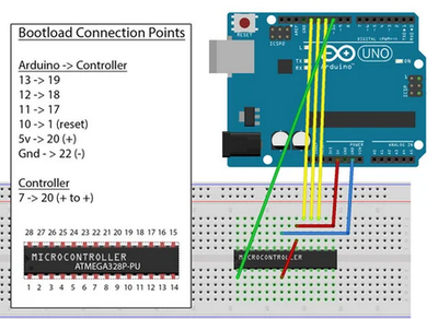
Originally I wired it per this schematic:
Which I got from this instructible. https://www.instructables.com/id/2-Arduino-the-ATMEGA328-As-a-Stand-alone-Easy-Chea/
Right now I will rewire the circuit using Steve's schematic.
but I think that the end result is that you will then be only able to run that chip at 8MHz.
You can change the bootloaders to your heart's content, no apparent restrictions on that.
The resistor I'm not sure of. It is needed for the programming, but once you are in production maybe it isn't needed either.
Not required in operational mode!
One thing I miss in your Fritzing diagram, are two ceramic caps (104) 0.1µF, placed between Vcc and Gnd as close to the ATmega328 pins as physically possible. The oscillator could be causing unnecessary noise in the circuit.
If I'm remembering correctly when using the FTDI programming route you also needed a cap on the reset line. But then again I have a hard time remembering what I had for lunch yesterday.
So you had the 16MHz crystal and some 22pf caps available? Or did you do it the 8MHz route?
SteveG
You can change the bootloaders to your heart's content, no apparent restrictions on that.
This is where it gets confusing to me! I knew you could go back and forth between either 8MHz or 16MHz bootloading, but where my confusion creeps in is that if you load the bootloader in 8MHZ mode, then you need to use the chip in a 8MHz design, and conversely if you used 16MHz mode then you couldn't use the chip in a circuit without a 16MHz crystal. Or do I have it all wrong?
SteveG
Have either of you tried using an FTDI adapter to upload? If not, how do you upload your sketches once the bootloader is on the ATMEGA328P-PU?
So I'm going through the boards one by one trying to upload the blink sketch to the ATMEGA328P-PU using an FTDI adapter. This is the schematic I'm using:
In DroneBot Workshop Bill shows the FTDI adapter pins starting at 32:15 into his video.
Bill Shows:
FTDI Pin DTR/RTS as Being 1st From Left (Facing Topside of Chip) Going to ATMega328 Pin 1 (Reset) Thru a 100 nF (104) Capacitor
FTDI Pin RX as Being 2nd From Left (Facing Topside of Chip) Going to ATMega328 Pin 3 (TX)
FTDI Pin TX as Being 3rd From Left (Facing Topside of Chip) Going to ATMega328 Pin 2 (RX)
FTDI Pin VCC as Being 4th From Left (Facing Topside of Chip) Going to +5 V (Can use same 5 V out of regulator supplying ATMega328)
FTDI Pin GND as Being 6th From Left (Facing Topside of Chip) Going to GND (Can use same GND out of regulator supplying ATMega328)
Pin 5 is Unused
I had the 16 MHz crystal and a whole bunch of 22 pF caps ready to go. I ordered like one 22 pF caps, 20 or 30 crystals, and like 10 of the ATMEGA328P-PU's having them all ready to go for future use in projects. I've got the 100 nF cap between the FTDI adapter DTR pin and Pin 1 of the ATMEGA328P-PU. I'm just working my way down the list of boards trying to find the right one.


