I got an Osoyoo robot car for Christmas! Pretty cool robot, but it didn't come with wheel encoders. I want to be able to program some maneuvers and I need a way to sense and calculate wheel rotation. I ordered a pair of T-Slot Photo Interrupters and encoder wheels from Adafruit. The description of the photo interrupter states, "The output transistor is open-collector, so you must connect a pullup resistor to your logic level". The robot car uses an Arduino Uno, so I'm going with a logic level of 5v. What value resistor should I use? I'm guessing a 1K or even a 10K ohm would work. Also, I'm guessing that I would connect the collector to an input to read a high or low signal? I like Adafruit, but they can be a little cavalier in their assumptions. I could do some bench testing to figure things out, but I would feel more confident with clearer instructions. This would also be the kind of thing I would like to see as beginning level material in this forum. Thanks, MT.
ZoolanderMicro, where small ideas are a big deal
Attached is the data sheet for the photo interrupter. The one I ordered is the EE-SX672-WR pre-wired with one meter cable.
ZoolanderMicro, where small ideas are a big deal
If it needs resistors I think 220 for the IR LED and 10K as a pull up resistor if using 5volts.
You can "see" IR light using your digital camera (unless it has an IR filter). I used that technique to identify the connections on some motorized wheels with built in encoders that I took from a second hand Roomba vacuum cleaner.
Have you watched this tutorial it might help?
https://dronebotworkshop.com/building-the-elegoo-smart-robot-car-part-1/
@robotbuilder Thanks, I ordered parts yesterday. They may arrive before the end of the week. Hopefully I will get a chance to try them out over the weekend.
ZoolanderMicro, where small ideas are a big deal
Actually the Roomba motorized wheels with encoders uses hall effect devices which are much easier to interface. I was thinking of the motorized wheels from another robotic vacuum cleaner that uses photo interrupters. I haven't worked on them for over 6 months and my memory fades.
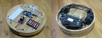
The reason I use parts from robotic vacuum cleaners is because they are of a much higher quality and cost a lot less than parts from toy robot sellers. I get a large battery, great geared wheeled motors with inbuilt encoders, a battery charging circuit with charger and various sensors.
My real interest is in programming and would be happy to buy an already constructed robot base.
Click right mouse button on image and choose open link in new window
@robotbuilder Nice! Motors with built-in encoders would be better than adding them on. I went with the optical encoder wheels because they fit easily onto the TT motor output shafts. I like your addition of a breadboard. I have room on the top level of the Osoyoo chassis to put a small breadboard. It could provide additional connections for power, lighting, sensors, speakers, etc. I will have to keep a lookout for robo-vacuums. Hobby robot chassis can be really expensive. I have been learning to use AutoCAD with the intent of using a laser cutter to make robot parts. This may take a while 😉
ZoolanderMicro, where small ideas are a big deal
You can always stack a larger breadboard on top.
One of the first things I did with my robot base using the encoders was testing dead reckoning programs. Seemed simple in theory but not so simple in practice. The first thing is to see if you can get it to drive itself in a straight line. Maybe then try going forward x distance and back x distance and see if it stops where it began. Then maybe negotiate a square. Forward x, turn right, Forward x, turn right, forward x, turn right, forward x, turn right and see if it also stops where it began. Even harder might be to follow curves like driving around a circle of some radius.
You can even play with vision based navigation with these simple bots although you would probably need a RPi as a controller.
My Osoyoo robot car is very much like the Elegoo robot car, though the Elegoo kit is more sophisticated. Notice the use of jumpers on my car. The Elegoo kit uses a shield with JST connectors which make the wiring easy and neat.
I ordered the photo sensors from Adafruit, but I had to order the encoder wheels from Digi-Key (Adafruit was out of stock). My Digi-Key order is waiting at the post office, but the sensors are still on the east coast. I will have to wait to try them out 🙁
ZoolanderMicro, where small ideas are a big deal
I received my photo sensors this weekend, and I have been making some modifications to the robot car to accommodate the additions. I used small washers as shims under the motor mounts to get enough clearance for the encoder wheels (~1.5mm). My original idea of using the motor mounts to secure the photo sensors wouldn't work, so I had to get creative.
I used blank perf-board to extend the mount. I'm still working out the design, but this is the general idea. I need to do some testing, and verify the clearance for the front-mounted, line following photo sensors.
Now I need to write a test routine to check the sensor alignment. It seems like every solution presents new challenges 🙂
ZoolanderMicro, where small ideas are a big deal

