Hi everyone,
I am Werner and I am new to the forum. I hope to get some assistance with a current circuit I am working on.
More specifically, I have been trying to build a 555 monostable circuit with a one button trigger for a servo motor to move from 0° to 90° and stay in place until I decide to again press the same button to move the servo motor from 90° to 0°. I have now watched countless videos and read for days on end to only sit with 2 burnt out servo motors and a partially one directional working circuit. I understand the idea behind the servo motor movement is greatly based on the PWM that is generated by the 555 timer but I just can not seem to get it right. I have now managed to get the servo motor to turn from 0° to 90° with the 1.1(RC) equation but I can not get it to turn again after it reached 90°. I have changed resistors and caps and tried changing both but failed. I have also read that the servo movement is dependent on the time output of pin 3, which I have gotten to be less than 1.25sec for counterclockwise movement and also more than 2.5 sec for clockwise movement. I have measured this with a multimeter and recorded the time of the circuit till it switches off but I can only seem to get once off one directional movement on the servo motor whereafter I need to reset the servo to 0° again with my arduino uno board.
I would greatly appreciate any possible pointers or direction on this.
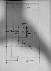
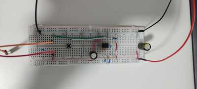
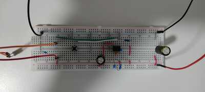
I have a pic of the circuit drawn out as well as the actual circuit attached
.
Part list:
555 Timer
10k Resistor
8.2k Resistor
18k Resistor
1000 uF 16v Capacitor
220 uF 50v Capacitor
3x 0.1 uF Capacitors
Push Button
Servo Motor (9g)
5v Power supply as main supply for entire circuit as well as Servo Motor.
@werner711 I can't see your circuit, there is a shadow across it and it is possibly too small. What if you turned it 90 degrees and either get closer or redraw it so that the big empty spaces on top and bottom are reduced?
First computer 1959. Retired from my own computer company 2004.
Hardware - Expert in 1401, and 360, fairly knowledge in PC plus numerous MPU's and MCU's
Major Languages - Machine language, 360 Macro Assembler, Intel Assembler, PL/I and PL1, Pascal, Basic, C plus numerous job control and scripting languages.
Sure you can learn to be a programmer, it will take the same amount of time for me to learn to be a Doctor.
@werner711 Could you save the cost of replacing burnt-out servos by using LEDs to test the circuit? Just stick a big resistor between the LED and supply voltage to stop it from burning out the LED.
First computer 1959. Retired from my own computer company 2004.
Hardware - Expert in 1401, and 360, fairly knowledge in PC plus numerous MPU's and MCU's
Major Languages - Machine language, 360 Macro Assembler, Intel Assembler, PL/I and PL1, Pascal, Basic, C plus numerous job control and scripting languages.
Sure you can learn to be a programmer, it will take the same amount of time for me to learn to be a Doctor.
@werner711 I can't see your circuit, there is a shadow across it and it is possibly too small.
Right click image, choose Open link in new window. You can enlarge the result even more with the magnifying glass symbol with + inside.
Where did you get the circuit schematic ?
Where does the arduino uno board come into the equation?
The position of a servo depends on the pulses per unit of time being sent to it.
So pressing the button should start the pulses at a frequency to move the servo 90 degrees and pressing it again should change the pulse frequency and the servo will move back to zero position.
You don't design a circuit by "trying" things so much as knowing exactly how it works and using a bit of math to determine the specifications of the components required.
You could use a latching push button that connect the power to the 56K with one push and then the 10K with another push.
https://www.engineersgarage.com/servo-motor-control-using-555-timer-ic/
@robotbuilder @werner711 Thanks, that helps quite a bit. It would be even better if the space above the chip and below R 10K was shrunk, there is a lot of white space there.
First computer 1959. Retired from my own computer company 2004.
Hardware - Expert in 1401, and 360, fairly knowledge in PC plus numerous MPU's and MCU's
Major Languages - Machine language, 360 Macro Assembler, Intel Assembler, PL/I and PL1, Pascal, Basic, C plus numerous job control and scripting languages.
Sure you can learn to be a programmer, it will take the same amount of time for me to learn to be a Doctor.
Hi @werner711,
Sorry, perhaps my grey cell is having a bad day, but I can't see how that circuit ... or 1 remotely like it, is going to do what you want.
I started by trying to simulate your circuit, which didn't look familar, and it did virtually nothing. Perhaps I made a mistake, I didn't spend too long trying to debug it.
-----------
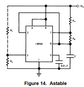
So I looked up the classic astable circuit. e.g. from https://www.ti.com/lit/ds/symlink/lm555.pdf
I simulated this circuit (with arbitrary R and C values) and it produced pulses, but when I came to select resistor and capacitor values to produce the pulse train with the correct timing for the servo, I hit the next problem ....
----------------
For this type of servo, according to https://components101.com/motors/servo-motor-basics-pinout-datasheet
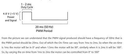
you need pulse reptition rate of 50Hz (20ms cycle), with a pulse length of 1ms for 0 degrees, and 1.5ms for 90 degrees, implying duty cycle of 1/20 = 5% and 1.5/20 = 7.5%
However, the 555 timer, in its normal astable configuration (ie without an extra diode or similar), cannot produce a duty cycle below 50%.
Alternate circuits with an extra diode or two are possible, which would probably fix this issue. (Or an inverter.)
e.g. see https://en.wikipedia.org/wiki/555_timer_IC#Shorter_duty_cycle
------------
Now of course these circuits only produce a fixed waveform, so by selecting Rs and Cs, it should be possible to get 20 ms cycle with ONE of either 1ms or 1.5ms high.
Furthermore, by means of additional switch and resistor, themselves in parallel with RA, it is possible to shorten the high time, although it will not lengthen the low time, so both the total cycle time and the duty cycle will change, but perhaps the servo motor will tolerate the cycle time change (I don't know.)
Now if you get this to operate, it will be at one angle WHILE the button is pressed (switch closed), the other angle WHILE the button is released (switch open).
--------
However in your description you say ...
I have been trying to build a 555 monostable circuit with a one button trigger for a servo motor to move from 0° to 90° and stay in place until I decide to again press the same button to move the servo motor from 90° to 0°.
This implies press once to go to 90 degrees, press again to go back to 0 degrees.
How you expect to get such a bistable action without a ADDITIONAL bistable circuit is beyond me.
---------
Sorry, I may have some errors, but I suspect you are trying to do the impossible, based on the resources you have.
-------------
I realise 555s can be persuaded to drive servos, and 45 years ago I would have considered such a path, albeit with at least an extra 555 or 74 series logic gate, but now I would generally look to a microcontroller such as the Arduino project supports as a much smarter and more flexible approach.
You might consider starting a new thread to describe why you need such a circuit function to see if anyone suggests a more radical approach.
-------------
Best wishes and good luck, Dave

