Hello all
I am trying to replicate a diagnostic machine used by VW in the 70s that plugged into a socket in the engine bay and ran a series of tests. (Lighting, battery, charging, grounding, dwell angle, ignition timing, compression) I am also adding an environmental module and some cameras.
I am planning to use a bunch of ESP32s
The first hurdle I would like to overcome is to carry out a continuity test on each of the 12 lighting circuits. The original wiring has a single test wire to the positive side of each lamp. The issue is I can't guarantee each circuit isn't live. i.e the lights may be switched on. So to test continuity I was thinking of first testing a circuit voltage, if the circuit is live then abandon the test, else test continuity along the test wire through the lamp to ground on the 12v battery. (A single output pin to the 12v ground and 12 input pins, one for each circuit.)
I have worked out how to test the voltage using a voltage divider. I have also worked out how to test continuity by first sending a HIGH signal from one pin and measuring it on another pin, then sending a LOW and checking again.
What I cant get my head around is how to do the voltage check followed by the continuity check using the same set of pins. I thought I had it worked out but then I cooked one of the ESP32s :o(
Any thoughts would be much appreciated.
I personally can't follow the problem. An actual circuit diagram probably help. I see this unsecure link has a page on the VW diagnostic socket for anyone with expertise in this area.
http://www.speedyjim.net/htm/plug.htm
Other links,
https://www.thesamba.com/vw/forum/viewtopic.php?t=720303
Section on VW Diagnosis plug here,
@robotbuilder Thanks for the reply, I will give one of the online drawing utilities a go and post a diagram
Cheers
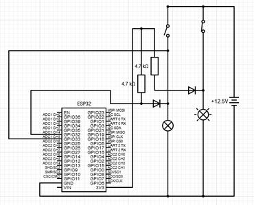
Here is a drawing of what I would like to do, however how best to protect the esp32 from 12v?
You could just use a pair of resistors (10K and 3.3K) to make a divider. Put them in series with the higher value to the positive end of the circuit and put the ESP32 pins from the junction with the other end going to ground (i.e. measure across the 3.3K resistor).
For 12V across the light, you'll get 12 x (3.3/13.3) = 2.98V reading on the ESP. If the battery delivers 13.5V (which should be the maximum possible) you'll read 13.5 x {3.3/13.3) = 3.35 V. Both should be within measurement range of your ESP.
If you don't care about an accurate voltage but just want to know that the light is being powered, then just choose two standard resistor values (larger values will reduce current drawn) whose ratio is greater than 6 or so. Again, put the smaller one across the ESP and the larger one towards the source.
Anything seems possible when you don't know what you're talking about.
Hi @tain,
It depends on what you fault you are looking for ... I am guessing in your case you expect the wiring and switches to be reliable, but the bulb filament may have failed. (It is a plausible, but by no means 100% accurate assumption!)
Oversimplistically, you might try something like:
The diodes are intended to block the 12V from reaching the ESP32.
This would be accompanied by an instruction of switch off all lights befor eactivating the diagnostics.
It will erroneously report the right hand bulb has failed, but when the mechanic goes to check, hopefully they will realise they forgot to switch it off! And the diode will have saved the ESP32.
----
Note that this circuit is probably too simplistic for a real car environment, since there are likely to be voltage spikes that could destroy the ESP32 inputs ... I would expect to see current limiting resistors and voltage clamps on the sensing inputs at least.
However, hopefully it gives you an idea to start with.
Best wishes, Dave
@davee , I was just looking at you schematic of the vehicle lights diagnostic, and noticed that the connection to Gpio33 looks to be in error.. should it not be connected as in the following drw..
LouisR
Hi @inst-tech ,
Thanks for spotting my mistake of only changing one of the GPIO connections from the questioner's original. Sorry, comes of adding content when I should I have retired for the night. 😴 😴
To clarify, the line from GPIO33 should be wired to the junction of 4k7 resistor and diode anode on the right hand side of the diagram.
Sorry for any confusion.
Best wishes, Dave
@davee , No worries Dave..if it weren't for making mistakes, I wouldn't learn anything!..LOL
As a process control tech for many decades, I was kinda use to checking up on my engineer colleagues as most of our field drawing were either out of date and in need of markup, or just simple mistakes that we all make.
BTW, I do appreciate all your comments, and trying to help people muddle through what must seem to them mystifying or magic... that's really what all this is about... getting people interested in do something positive and worth while. Keep up the great work!
regards, LouisR
LouisR
@robotbuilder thanks for these links, I hadn’t seen the third one before, lots of useful thoughts
@will thanks, I have some voltage divider boards with 7.5 and 30 resistors. The voltage when the engine is running an be around 14.5v so these should do the job.
@davee thanks, I have some voltage dividers and will order some diodes and try again :0)
Hi @tain,
In a vehicle system, if there is a chance that your system will be connected when the engine is started or running, it is important to protect against transients .. the voltage may exceed 14V for short pulses.
Sadly, I am having difficulty finding a good, straightforward reference on the web, as it is an area that involves experience as well as the simple 'textbook' approach.
As a start, have a read:
https://www.digikey.co.uk/en/articles/protecting-inputs-in-digital-electronics
.. particularly figure 11 section onwards. Remember ESP voltage rails are 3.3v instead of 5V, but otherwise it should all be applicable.
Their solutions maybe a little 'over the top', but try to understand the discussion and the aims - that way you can begin to formulate your own solutions. And be prepared for the occasional damaged chip as part of the experience learning curve... 😪
As a minimum, if you are effectively measuring the battery voltage, then start with a potential divider .. as @Will described, though I would respectively suggest using a 2.7k resistor instead of the 3.3K, to cover voltages above 14V, the case when the engine is running, then add the two Schottky diodes shown in figure 11 of the reference above, the centre point of the diodes being connected to centre point (output) of the potential divider.
Best wishes, Dave


